Catalina - Capri - 25s International Assocaition Logo(2006)  
Assn Members Area · Join
Association Forum
Association Forum
Home | Profile | Register | Active Topics | Forum Users | Search | FAQ
Username:
Password:
Save Password
Forgot your Password?

 All Forums
 Catalina/Capri 25/250 Sailor's Forums
 Catalina 25 Specific Forum
 Transom Damage (and fiberglass repair).
 New Topic  Topic Locked
 Printer Friendly
Author Previous Topic Topic Next Topic  

odonnellryanc
Navigator

Member Avatar

108 Posts

Initially Posted - 12/06/2017 :  23:54:25  Show Profile
I knew this buying the boat, but after giving it a look it didn't seem so bad. Well, it was a little worse than I expected!

Basically, the damage seemed to be some crushed glass. Was interesting ... was more of a large spot of soft glass than cracks. I didn't really see any large cracks.

After pulling out everything that seemed damaged I laid glass from behind the transom (rough job in a tight place ... ) and MANY sheets on the outside.

Here's a gallery: https://imgur.com/a/WW3ik

Do I have anything to worry about with this type of damage? I'm going to install backing brackets to the inside of the transom when I put the new motor mount on.

Having fun restoring this C25! :)

JB
Navigator

Members Avatar

USA
110 Posts

Response Posted - 12/07/2017 :  12:24:34  Show Profile
It looks like you have done a fine job. I'm surprised at the apparent lack of fiber and the pock marked appearance in the before image. It doesn't look like Catalina reinforced this area for the motor mount. I've got some oil canning under the mount and I'm wondering if I should beef it up before the glass is too badly decomposed.

1988 C25 Wing Keel Std Rig Tohatsu 9.9 Tiller Steering and 2003 C250 Wing Keel Std Rig Inboard Diesel Wheel Steering
Go to Top of Page

Stinkpotter
Master Marine Consultant

Members Avatar

Djibouti
9013 Posts

Response Posted - 12/07/2017 :  13:38:14  Show Profile
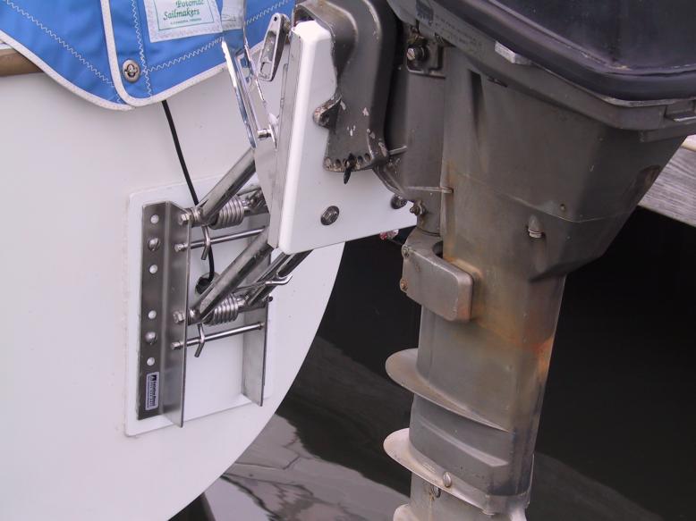
Several of us mounted our outboard brackets on Starboard plates on the outside of the transom to spread the load of the outboard bracket over the fiberglass. I made mine to extend below the bracket to support the leveraged force of the motor under way as well as the weight on the bracket. In my 1985, there was only some foam between the outer shell of the transom and the interior molding. I saw no signs of oil-canning, but I was replacing the outboard with a new, heavier one, and a sturdier bracket.

Dave Bristle
Association "Port Captain" for Mystic/Stonington CT
PO of 1985 C-25 SR/FK #5032 Passage, USCG "sixpack" (expired),
Now on Eastern 27 $+!nkp*+ Sarge

Edited by - Stinkpotter on 12/07/2017 13:40:00
Go to Top of Page

OLarryR
Master Marine Consultant

Members Avatar

USA
3367 Posts

Response Posted - 12/08/2017 :  04:55:00  Show Profile  Visit OLarryR's Homepage
I would definitely use a piece of Starboard as reinforcement when mounting your outboard bracket. It is easy enough and adds some stiffening to the area. I used a rather thin Starboard sheet. I cannot recall what thickness I used and from the below photo, it is hard to tell - Either an 1/8" or a 1/4". Considering the issues you had, you may want to go with at least a 3/8" thickness. But any thickness will be of benefit.


Larry
'89 Robin's Nest#5820, Potomac River/Quantico, Va
http://catalina25.homestead.com/olarryr.html
Go to Top of Page

JB
Navigator

Members Avatar

USA
110 Posts

Response Posted - 12/08/2017 :  05:22:32  Show Profile
My transom has a slight curve and I also used a thin piece of starboard to re-attach the motor mount because a thicker piece would not conform to the curve of the transom. When I use high thrust it pushes the transom inward slightly. I did not have any foam between the hull and liner there was a gap. I've never read about motor mounts failing but this area does not appear to be reinforced. Would it be over-kill or make things worse to cut away the liner and glass in a piece of G10 to the hull? From the pattern in the original poster's pictures it looks that boat had the heavier mount attached without starboard as reinforcement and flexing or movement of some kind was wearing a hole.

1988 C25 Wing Keel Std Rig Tohatsu 9.9 Tiller Steering and 2003 C250 Wing Keel Std Rig Inboard Diesel Wheel Steering
Go to Top of Page

Stinkpotter
Master Marine Consultant

Members Avatar

Djibouti
9013 Posts

Response Posted - 12/08/2017 :  07:51:32  Show Profile
I made my plate to extend out to a curve close to the edge of the hull where it is structurally very stiff. I expected the inward pressure to be at the bottom of the bracket, while the top will be pulling outward. Your picture supports that theory... I made a backing plate for the upper bolts inside. (I may have used just fender washers for the lower bolts--not sure.) An inside backing plate should have rounded corners and edges because of the slight concave curve. The slight convex curve outside wasn't a problem, and my plate was a little wider than Larry's. Some Life Seal gave it a good bed.

Dave Bristle
Association "Port Captain" for Mystic/Stonington CT
PO of 1985 C-25 SR/FK #5032 Passage, USCG "sixpack" (expired),
Now on Eastern 27 $+!nkp*+ Sarge

Edited by - Stinkpotter on 12/08/2017 07:57:05
Go to Top of Page

islander
Master Marine Consultant

Members Avatar

USA
3992 Posts

Response Posted - 12/08/2017 :  11:52:45  Show Profile
Since its a repaired area I would go with the plate on both outside and inside. Dave's right in making the outside extend lower to cover as much area as you can to spread the load. A full plate on the interior just because you can never have enough support. Obviously you will need longer bolts.

Found a photo of Davids(dmpilc) plates.
quote:
I also used Starboard on both sides of the transom, 1/2" on the outside and 1/4" inside.


Scott-"IMPULSE"87'C25/SR/WK/Din.#5688
Sailing out of Glen Cove,L.I Sound


Go to Top of Page

JB
Navigator

Members Avatar

USA
110 Posts

Response Posted - 12/08/2017 :  12:21:04  Show Profile
Dare I say that while you've got your angle grinder out and epoxy supplies handy have a look at your gudgeons, especially the lower one.

1988 C25 Wing Keel Std Rig Tohatsu 9.9 Tiller Steering and 2003 C250 Wing Keel Std Rig Inboard Diesel Wheel Steering
Go to Top of Page

odonnellryanc
Navigator

Members Avatar

108 Posts

Response Posted - 12/08/2017 :  13:18:06  Show Profile
JB, gudgeons are in good shape, but I actually have a spare set that I'm going to install so I have 3.

However, I did take the opportunity to repair some other parts of the boat. Namely some glass work around the stern pulpit stanchions. Fun job ;)

I'll make sure to include the exterior backing board. Great idea! I already have steel L-brackets for the interior, and I feel those would work just as well (or better?) so I'm thinking of using those.

Thanks again everyone, awesome comments.
Go to Top of Page

islander
Master Marine Consultant

Members Avatar

USA
3992 Posts

Response Posted - 12/08/2017 :  15:05:32  Show Profile
I used large angle aluminum brackets on my interior just because I had the stock. The stock is the same if not larger then the aluminum angle backing plates used for the shrouds.

Scott-"IMPULSE"87'C25/SR/WK/Din.#5688
Sailing out of Glen Cove,L.I Sound


Go to Top of Page

Frank Law
Navigator

Members Avatar

USA
159 Posts

Response Posted - 12/09/2017 :  20:02:58  Show Profile
I just used Plywood on the inside covering all four bolts'

Frank Law
Former c25 sailor
Go to Top of Page
  Previous Topic Topic Next Topic  
 New Topic  Topic Locked
 Printer Friendly
Jump To:
Association Forum © since 1999 Catalina Capri 25s International Association Go To Top Of Page
Powered By: Snitz Forums 2000 Version 3.4.06
Notice: The advice given on this site is based upon individual or quoted experience, yours may differ.
The Officers, Staff and members of this site only provide information based upon the concept that anyone utilizing this information does so at their own risk and holds harmless all contributors to this site.