Catalina - Capri - 25s International Assocaition Logo(2006)  
Assn Members Area · Join
Association Forum
Association Forum
Home | Profile | Register | Active Topics | Forum Users | Search | FAQ
Username:
Password:
Save Password
Forgot your Password?

 All Forums
 Catalina/Capri 25/250 Sailor's Forums
 Catalina 25 Specific Forum
 Mast lights
 New Topic  Topic Locked
 Printer Friendly
Author Previous Topic Topic Next Topic  

jaydon
Navigator

Member Avatar

USA
156 Posts

Initially Posted - 04/24/2015 :  06:26:50  Show Profile
This went to the 250 forum in error.
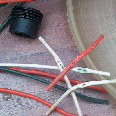
OK, all the lights in the cabin work. Fwd & aft nav lights work. However, none of the lights on the mast work. The deck fitting looked like hell. I want to test with a multimeter, but everything i've read makes me think I need a degree in Elect Eng.
I think I have to check continuity and resistance at the mast plug and voltage at the deck side of the plug.
For the voltage check- do I just put thy black lead in the ground 'hole' in the plug and then the red into each of the others in turn? (with power to the plug?)
Resistance only on the mast plug?
Is this ground to each or every pin to each pin to each pin?
What should this reading be for good? I think it should be "0"?
Just looking for a layman's answer on this. LOL
Jay

Jay
South County RI
Cat 25 SR/FK/Trad
#5645
Wind Dancer

dasreboot
Admiral

Members Avatar

803 Posts

Response Posted - 04/24/2015 :  06:45:00  Show Profile  Visit dasreboot's Homepage
basically yes. that will tell you voltage at the female socket. you also have to check resistance at the male end from the mast. you could probably just check resistance between ground and power wire for each bulb. that's the correct way to troubleshoot. break each circuit into steps and test each.

Todd Lewis
Eowyn 87 TR/WK C25 #5656
ARWEN 84 TR/SK C25 #4031
www.mainsailsailingschool.com
Go to Top of Page

redeye
Master Marine Consultant

Members Avatar

3475 Posts

Response Posted - 04/24/2015 :  06:47:03  Show Profile
<< I want to test with a multimeter, but everything i've read makes me think I need a degree in Elect Eng. >>

Nope...

<< For the voltage check- do I just put thy black lead in the ground 'hole' in the plug and then the red into each of the others in turn? (with power to the plug?) >>

Yep...

<< Resistance only on the mast plug? >>

Yep.. if the light bulbs are working.

<< Is this ground to each or every pin to each pin to each pin? >>

power to ground for each circuit. The amount of resistance, or simply any continuity shows the circuit is working.

<< What should this reading be for good? I think it should be "0"? >>

Continuity is not a reading, it is or isn't .. if the meter beeps it connects, it is continuous, the wires connect throughout the circuit from power to ground.

Reading the resistance is pretty much not what you ( layman ) do, you just see if you have continuity or not, and also if the bulb is blown you will most often not have continuity. The filament will break completely.

Resistance reading is pretty much a function of the filament in the bulb giving some amount of resistance, and it creates heat and light in doing so. I don't know what that reading should be.

<<Just looking for a layman's answer on this. LOL >>

Ray in Atlanta, Ga.
"Lee Key" '84 Catalina 25
Standard Rig / Fin Keel

Edited by - redeye on 04/24/2015 07:32:59
Go to Top of Page

redeye
Master Marine Consultant

Members Avatar

3475 Posts

Response Posted - 04/24/2015 :  07:25:26  Show Profile
I had a little problem with the wires in the deck leading to the plug getting crushed together and power was going from one circuit to another.. So keep that in mind when you test. If you get power to one circuit ( when one switch is on ) and again power to that circuit ( again with another switch on ) the wires may be shorting to each other.

Or you switch on one switch and two circuits have power.

That drove me crazy for a while... I'd turn on the steaming light and the see the deck light was on and get confused about which switch was which...


Ray in Atlanta, Ga.
"Lee Key" '84 Catalina 25
Standard Rig / Fin Keel
Go to Top of Page

dasreboot
Admiral

Members Avatar

803 Posts

Response Posted - 04/24/2015 :  08:39:52  Show Profile  Visit dasreboot's Homepage
I am sold on these now. puts all the connections inside the cabin. very easy to test.

http://www.westmarine.com/buy/blue-sea-systems--cableclam-waterproof-through-deck-fittings--P003_094_003_008

Todd Lewis
Eowyn 87 TR/WK C25 #5656
ARWEN 84 TR/SK C25 #4031
www.mainsailsailingschool.com
Go to Top of Page

islander
Master Marine Consultant

Members Avatar

USA
4009 Posts

Response Posted - 04/24/2015 :  09:04:23  Show Profile
quote:
I had a little problem with the wires in the deck leading to the plug getting crushed together and power was going from one circuit to another.. So keep that in mind when you test. If you get power to one circuit ( when one switch is on ) and again power to that circuit ( again with another switch on ) the wires may be shorting to each other.

I would like to meet the "Popeye" at Catalina that decided to bury the wire cable between the deck and the bulkhead...What a bonehead...

Scott-"IMPULSE"87'C25/SR/WK/Din.#5688
Sailing out of Glen Cove,L.I Sound


Go to Top of Page

DavidBuoy
Admiral

Members Avatar

USA
707 Posts

Response Posted - 04/24/2015 :  10:04:10  Show Profile
quote:
Originally posted by islander


I would like to meet the "Popeye" at Catalina that decided to bury the wire cable between the deck and the bulkhead...What a bonehead...


I agree. Everything else is run inside the cabin, why would you do that?? maybe to keep wiring that is going up the mast separate incase of a lightning strike, i dont know. I just replaced all of my wiring in the cabin, in the mast, deck connector and all new fixtures and it feels great. Can't wait to use the new deck light!


Captain Rob & Admiral Alyson
"David Buoy"-1985 C25 SK/SR #5053

Edited by - DavidBuoy on 04/24/2015 10:04:39
Go to Top of Page

islander
Master Marine Consultant

Members Avatar

USA
4009 Posts

Response Posted - 04/24/2015 :  10:23:23  Show Profile
quote:
maybe to keep wiring that is going up the mast separate incase of a lightning strike,

I doubt that.. probably more about the aesthetics and having a cleaner look. Exposed wiring is ugly to a new buyer.

Scott-"IMPULSE"87'C25/SR/WK/Din.#5688
Sailing out of Glen Cove,L.I Sound


Go to Top of Page

redeye
Master Marine Consultant

Members Avatar

3475 Posts

Response Posted - 04/24/2015 :  10:42:04  Show Profile
<< I would like to meet the "Popeye" at Catalina that decided to bury the wire cable between the deck and the bulkhead...What a bonehead... >>

Now Scott.. I'm sure some retired engineer is gonna read that and think the same about you ..

Just think... those wires worked just fine for over 25 years, in fact I never did replace all of my cabin lighting circuit so that wiring is powering my LEDs after 30 years...

Dasreboot.. I agree with you .. using a through hull and connections on the inside is a great idea. Thanks for pointing that out. Of course it would depend on how often you hafta drop and relocate the stick.

Ray in Atlanta, Ga.
"Lee Key" '84 Catalina 25
Standard Rig / Fin Keel
Go to Top of Page

jaydon
Navigator

Members Avatar

USA
156 Posts

Response Posted - 04/24/2015 :  11:02:46  Show Profile
Well, checked the connections today. The half of the fitting from the mast is 'toast'! Ordered a new fitting. We'll see how it goes with that rteplaced.
Jay

Jay
South County RI
Cat 25 SR/FK/Trad
#5645
Wind Dancer
Go to Top of Page

dasreboot
Admiral

Members Avatar

803 Posts

Response Posted - 04/24/2015 :  11:05:44  Show Profile  Visit dasreboot's Homepage
quote:

Dasreboot.. I agree with you .. using a through hull and connections on the inside is a great idea. Thanks for pointing that out. Of course it would depend on how often you hafta drop and relocate the stick.


adds about 10 min (going slowly) for my once a year lowering. no more corroded pins!

Todd Lewis
Eowyn 87 TR/WK C25 #5656
ARWEN 84 TR/SK C25 #4031
www.mainsailsailingschool.com
Go to Top of Page

islander
Master Marine Consultant

Members Avatar

USA
4009 Posts

Response Posted - 04/24/2015 :  11:37:18  Show Profile
quote:
The half of the fitting from the mast is 'toast'!

$10 bucks says thats your problem but if not I left a post on the 250 forum. To have all the mast lights out means that the ground wire is broken or corroded in that plug.

Scott-"IMPULSE"87'C25/SR/WK/Din.#5688
Sailing out of Glen Cove,L.I Sound


Edited by - islander on 04/24/2015 11:46:46
Go to Top of Page

glivs
Admiral

Members Avatar

USA
836 Posts

Response Posted - 04/24/2015 :  17:47:13  Show Profile
Like others have noted it is likely the ground receptacle is corroded...a common problem. Opinions differ on how but clean the receptacles (female side) using emory cloth, isopropyl alcohol or electronic cleaner. On mine, the ground is the larger pin but you should confirm your own wiring. With your multimeter check the voltage of each outlet against the common ground and map them with each switch. They should all read within a few percent of your battery voltage and if there is no cross talk, only one should register at a time. Once the receptacle is clean and tested, seal the outlets with dielectric grease before inserting the male half of the connector. This will greatly reduce corrosion and if you do not drop the mast, i.e. leave the connector disconnected for long, should last a few seasons depending on your environment.

Gerry Livingston, Malletts Bay, VT
"Great Escape" 1989 C-25 SR/WK #5972

Edited by - glivs on 04/24/2015 17:49:04
Go to Top of Page

Voyager
Master Marine Consultant

Members Avatar

USA
5308 Posts

Response Posted - 04/24/2015 :  21:24:58  Show Profile
I'm pretty confused with all the ifs, ands and buts... I think there should be a few basic steps troubleshooting this problem.
1. Do you have a good cabintop receptacle (all pins physically intact and clean, shiny metal) and
2. Do the switches for the bow light and anchor light produce 12v between the "hot" pin and the ground pin?
If not, fix it. If these are all right then proceed to the next steps:
3. On the plug side, there should be one common ground pin, one anchor light pin and one bow light pin. Check that each pin is clean and shiny.
4. If you have incandescent bulbs, to test continuity, set the ohmmeter to 1 Ohm or the "continuity" setting.
> When you test between ground and the anchor light lead, you'll get one of two responses:
A. Zero Ohms (or like 0.5 Ohms) (good) or
B. infinity Ohms (bad).
Different meters display an open circuit as -- -- -- or X X X.
> Do the same between the bow light lead and ground.
5. If you have LED lights up the mast, it's a little more complicated.
I use a fresh 9V (square) battery and connect the minus (-) lead to ground and the plus (+) lead to the anchor lead. If the LED lights up, the circuit is good. Do the same for the bow light lead and ground lead.
[Warning - some LED brands will not light using a 9V battery, but most will].


Bruce Ross
Passage ~ SR-FK ~ C25 #5032

Port Captain — Milford, CT
Go to Top of Page

jaydon
Navigator

Members Avatar

USA
156 Posts

Response Posted - 04/26/2015 :  06:18:03  Show Profile
Good morning,
As I posted I ordered the new deck fitting. The half from the mast was really bad. Since I get both halves, I'd like to do them both. When I talked to CD, they told me the wires inside the boat are buried in the fiberglass.
My question is - is there slack in the wire beneath the deck half so that it can be changed?
I know i'll find out soon enough, but like to have as much info as possible before I start anything. Just my way, I guess.
Jay

Jay
South County RI
Cat 25 SR/FK/Trad
#5645
Wind Dancer
Go to Top of Page

GaryB
Master Marine Consultant

Members Avatar

USA
4298 Posts

Response Posted - 04/26/2015 :  09:13:02  Show Profile
quote:
Originally posted by jaydon

Good morning,
As I posted I ordered the new deck fitting. The half from the mast was really bad. Since I get both halves, I'd like to do them both. When I talked to CD, they told me the wires inside the boat are buried in the fiberglass.
My question is - is there slack in the wire beneath the deck half so that it can be changed?
I know i'll find out soon enough, but like to have as much info as possible before I start anything. Just my way, I guess.
Jay


On my '89 there was very little slack to change out the connector. I was able to do it but it was very tight.

A few have been able to pull new wire thru the overhead, most others have had to run new wiring behind the port side settee into the head area and then go up at an angle thru the overhead to come out in the same hole in the deck.

If I remember correctly, OLarryR shared his upgraded wiring process with us several years ago. Use the search function above to find it.


Association Member

GaryB
Andiamo
'89 SR/WK #5862
Kemah,TX

Edited by - GaryB on 04/26/2015 09:16:15
Go to Top of Page

jaydon
Navigator

Members Avatar

USA
156 Posts

Response Posted - 04/26/2015 :  10:36:37  Show Profile
Gary
That's what I figured. Every time I talk with CD; they stress that these boats were made individually. So, i'm hoping that mine will be the one with a couple of inches of wire that I will be able to cut and re-attach.
Jay

Jay
South County RI
Cat 25 SR/FK/Trad
#5645
Wind Dancer
Go to Top of Page

wanderer13
1st Mate

Members Avatar

USA
76 Posts

Response Posted - 04/27/2015 :  19:57:16  Show Profile
After 30 years, your mast lights should probably be re-wired and the deck plug replaced. As previously stated, it will be near-impossible to snake new wire through the overhead. When I rewired my mast, I ran new wire through flexible conduit along the top of the bulkhead and then down underneath the port settee to the breaker.
Go to Top of Page

jaydon
Navigator

Members Avatar

USA
156 Posts

Response Posted - 04/27/2015 :  21:52:14  Show Profile
Yeah, Rewiring is on the horizon. For this year it will be the deck connection first. Hope that does it.
Jay

Jay
South County RI
Cat 25 SR/FK/Trad
#5645
Wind Dancer
Go to Top of Page

Voyager
Master Marine Consultant

Members Avatar

USA
5308 Posts

Response Posted - 04/28/2015 :  07:21:58  Show Profile
As I recall the discussion, the wires in one case took a lot of tugging and shooting silicone spray and finally came loose enough to get a few inches of slack on the top at the deck fitting.
Someone else bought an extra-long 1/2" drill bit, angled it almost horizontal and was able to drill a channel from the top deck fitting down into the head area directly in front of the midships bulkhead.
The direct approach of course is to drill straight down under the deck fitting, but then you've got a wire hanging loose in the head that you'd have to dress and route.
Another approach is to cap over the old deck fitting and place a new one directly above the bulkhead, then make sure your mast cable will reach it and stay out of the way as a trip hazard.
Thankfully I was able to use the short bits of wire I had to clean up the connections and replace the fitting.

Bruce Ross
Passage ~ SR-FK ~ C25 #5032

Port Captain — Milford, CT
Go to Top of Page

OLarryR
Master Marine Consultant

Members Avatar

USA
3408 Posts

Response Posted - 04/28/2015 :  10:22:04  Show Profile  Visit OLarryR's Homepage
Agree with many of the comments. My wiring has all been replaced including the deck connector and I added fans and a new switch panel. My initial issue was the wires inside and attached to the deck connector had deteriorated and a 1/2" needed to be cut off and the wires re-connected. I found that there was not enough slack in the wires to make up the connection with the existing inside wires. (On my connector, one wire was the common ground, then 3 positives for the anchor, and combo steaming/deck lights housings. Once I replaced the wires leading into the cabin (and I'll explain what I did below), I then found when removing the existing wires which ran from the original switch panel, then adjacent to the bilge cover and then up the mast column, that the existing wires were not actually embedded in the fiberglass in the cabin top but were very snug. From the bilge, I gave a tug on the existing wires and they dropped down the mast column and removed it. But the access is so snug, that threading up replacement wires would probably be difficult and most likely impossible. But I had not realized the wires were not embedded until after I had already resolved installing the new wires.

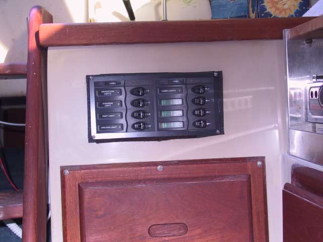
I had bought an "Anchor" brand mast wire which had 5 wires in a round sheath. I was using the 5th wire as a positive lead for a fan that I located on the mast column facing the main cabin. The biggy was how to get that wire up to the original deck connector. I purchased drill bit with a long shaft and drilled at a significant angle thru the deck connector opening angling the drill bit forward with intention to have the hole come out just forward of the cabin bulkhead so that the hole would be in the top of the Head area of the cabin. The drill bit was way long enough and I knew the hole was drilled thru but I could not find it in the cabin top. Finally, I spotted a cut (that was the drilled hole) in the small rubber liner that covers up the bulkhead joint to the head compartment cabin top ! I then drilled a hole behind the head adjacent to the bulkhead wall into the shelf that is behind the head. I threaded the mast wire thru the deck connector hole I had drilled and then attached clips to hold the wire against the cabin liner at the top dropping the wire thru the hole in the shelf behind the head. from there, I pulled it thru under the seats in the main cabin and attached the leads to the new switch panel I installed on the front panel of the sink adjacent to the companionway (Photos on my website of the new switch panel). In this way, I no longer had to go into the cabin and fiddle with the old switch panel when nav llghts needed to be turned on. I could simply reach into the companionway while still sitting on the cockpit seats and turn the nav lights on from the new panel.

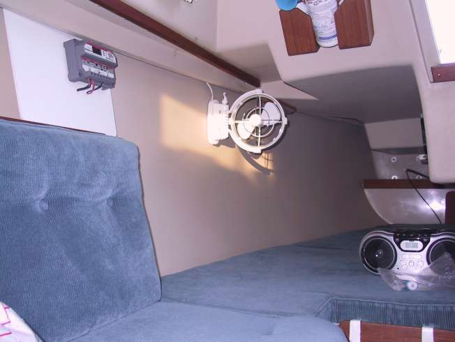
The 5th wire, I exited it out from the mast wire near the cabin top where the mast wire entered the Head Compartment and then cut it appropriately to hook up my fan. I forget where I hooked up the fans negative terminal, I may have hooked it up to the single ground within the mast wire or ran a separate ground for it. I then hooked up another fan in the quarter berth area which can be angled forward for cooling in the main cabin. It's wires were then run also to the new switch panel.

I still have some loads on my existing panel that is under the steps but nav lights, fans and cabin lights were moved the new switch panel.

Larry
'89 Robin's Nest#5820, Potomac River/Quantico, Va
http://catalina25.homestead.com/olarryr.html

Edited by - OLarryR on 04/28/2015 10:27:33
Go to Top of Page

Voyager
Master Marine Consultant

Members Avatar

USA
5308 Posts

Response Posted - 04/28/2015 :  21:10:09  Show Profile
Larry
Thanks for reviewing your procedure. I did recall you using that long drill to make a new channel and things worked out better than expected. To also get a fan control on top of that is brilliant.
I installed a 12VDC lighter plug mounted near the head sink to plug in my H2O fan. Having another fan in the Q'berth is great. Stuffy in there on a hot night!

Bruce Ross
Passage ~ SR-FK ~ C25 #5032

Port Captain — Milford, CT
Go to Top of Page

OLarryR
Master Marine Consultant

Members Avatar

USA
3408 Posts

Response Posted - 04/29/2015 :  03:48:20  Show Profile  Visit OLarryR's Homepage
Bruce - Thanks for comments.

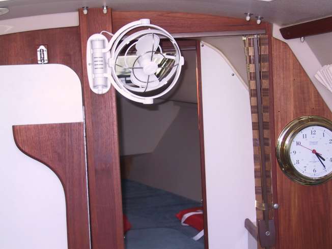
You mentioned about the accessory plug you added near the Head sink for a fan. I did something similar but was mainly thinking about anyone wanting to plug in an accessory in the main cabin forward adjacent to the bulkhead to Head sink - for anyone seated or sleeping on the main cabin starboard side cushion. So, I added a 12 volt plug adapter in the main cabin below the forward end of the cushion. But....to tell you the truth, I and no one else has ever used that adapter I added. I was checking my website and I do not have a photo of that adapter but decided to add below, the photos of the fans. These are Caframo Scirroco fans. I used them because they can be swiveled in all 3 directions, allowing them to be swiveled out of the companionway (and locked) when the fan is not used, angled up or down depending on preference and fan cage turned 360 degrees to angle it left or right independent of the entire frame being swiveled. Also, these fans have 3 speeds and generally the lowest speed is the only one to use and never the highest speed. These fans also have a timer device allowing them to auto shut off if set for 2, 4 or 6 hours running time. The fan in the quarterberth, while very useful to cool down the quarterberth is actually used much more to provide addl cooling up forward for the main cabin. That way both fans are utilized for a comfortable main cabin area (and also the quarterberth). The fan on the mast column can also be used for the VBerth by swiveling the fan blades around....but never use the VBerth for sleeping.


Larry
'89 Robin's Nest#5820, Potomac River/Quantico, Va
http://catalina25.homestead.com/olarryr.html

Edited by - OLarryR on 04/29/2015 03:51:13
Go to Top of Page

OLarryR
Master Marine Consultant

Members Avatar

USA
3408 Posts

Response Posted - 04/29/2015 :  03:56:28  Show Profile  Visit OLarryR's Homepage
Off topic

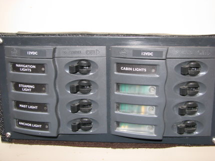
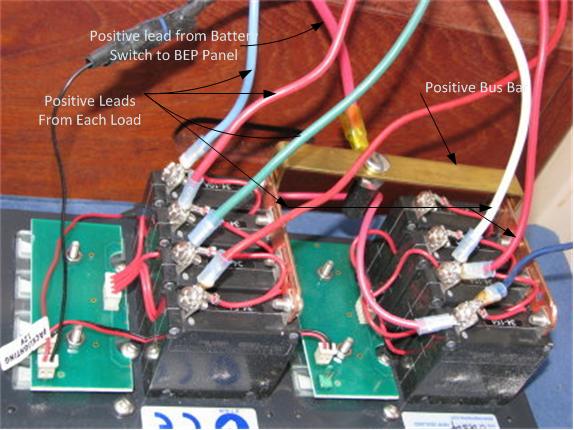
While I am at it, here are some addl details of the wiring/new switch panel installed. The switch panel, well not new any more, is a BEP 8 switch-circuit breaker horizontal panel. I have it set up that when the cabin light switch is turned on, then the entire panel labels light up. When the cabin light switch is off, then the labels are not lighted but each switch has an LED for indicating when it is individually turned on. The BEP panels come from Australia but are available thru some USA distributors. I liked the appearance of the panel and how the switches are laid out with the front facing. But the main reason I went with this panel was due to the clearances/footprint of the inner workings with how it would fit into the front panel below the sink and not interfere with the sink bowl. The BEP Panel had the shortest depth/smaller inside footprint compared to other panels I had considered. As an extra precaution regarding any metal to metal contact or chance of a spark jump, I double or triple layered the bottom of the sink bowl with thick rubberized tape entirely covering the area in close proximity to the outer perimeter of the inner workings of the switch panel. (I would estimate with the tape installed, the electrical panel box comes within 1/4-3/8" close to the sink bowl.)


Larry
'89 Robin's Nest#5820, Potomac River/Quantico, Va
http://catalina25.homestead.com/olarryr.html

Edited by - OLarryR on 04/29/2015 04:10:43
Go to Top of Page
  Previous Topic Topic Next Topic  
 New Topic  Topic Locked
 Printer Friendly
Jump To:
Association Forum © since 1999 Catalina Capri 25s International Association Go To Top Of Page
Powered By: Snitz Forums 2000 Version 3.4.06
Notice: The advice given on this site is based upon individual or quoted experience, yours may differ.
The Officers, Staff and members of this site only provide information based upon the concept that anyone utilizing this information does so at their own risk and holds harmless all contributors to this site.