Catalina - Capri - 25s International Assocaition Logo(2006)  
Assn Members Area · Join
Association Forum
Association Forum
Home | Profile | Register | Active Topics | Forum Users | Search | FAQ
Username:
Password:
Save Password
Forgot your Password?

 All Forums
 Catalina/Capri 25/250 Sailor's Forums
 Catalina 25 Specific Forum
 internal halyards
 New Topic  Topic Locked
 Printer Friendly
Author Previous Topic Topic Next Topic  

tomh
1st Mate

Member Avatar

USA
83 Posts

Initially Posted - 05/19/2013 :  06:55:07  Show Profile
Hello all,

I'm getting ready to update and run halyards internally. I watched the video from CD for the C22 upgrade, ordered the kit, and read the instructions in the box.

Any advise or words of wisdom before I start?

Tom

1978 C25 "Karma" #790
Toledo Beach Marina
LaSalle, Michigan

Edited by - on

pastmember
Master Marine Consultant

Members Avatar

2402 Posts

Response Posted - 05/19/2013 :  07:01:12  Show Profile
The lower the exit box the less tripping hazard there is. The stock Catalina position is too high in my estimation. I still ran my stock ones through turning blocks at the mast base to get a more fair lead to the deck organizer and reduce the tripping hazard. If you don't have a mast/halyard plate at the base of your mast get one.

Edited by - pastmember on 05/19/2013 07:01:36
Go to Top of Page

MrKawfey
Navigator

Members Avatar

USA
124 Posts

Response Posted - 05/25/2013 :  09:02:35  Show Profile
I ran mine internally a couple of years ago and there are several things I would do differently for sure. First a quick recap of the project:
I was looking to have the ability to have more than 2 lines running up the mast which is what spurred the project. The only way to do this is to use the 4 sheaves for one line each instead of two per line. (actually you can hang a block out on the masthead as a crane, but that's a different story) Once you make that leap, the only place for the line to go after it runs over the sheave is down the mast.
I didn't use their kit, but I used similar components. At the same time I rewired the mast and added the pvc wiring conduit. I already had the halyard plate installed.

Here are some notes about things I learned:
1) BALL BEARINGS! especially if you are running lines aft. You will be adding a lot of friction to the system and if you don't use ball bearing type blocks and sheaves you will regret it.

2) You HAVE to do something with the wiring in the mast. My original wiring had foam pieces taped to it every couple of feet to keep it from slapping in the mast. At first I thought the PO did this, but after reading some posts on this forum I get the sense that Catalina did several different things over the years to pad the wiring. Without removing this foam I would not have been able to run the halyards. It was not possible to remove the foam without removing the entire wiring harness.

3) I used a pair of the double exit blocks because I ran 3 lines up the mast (true topping lift, main and jib halyards and space for a fourth if I need it). Frank hit the nail on the head, if you are using the blocks, get them as low as possible. Here's the problem, the exit blocks the sell on Catalina Direct aren't really designed to turn a line through a small angle (less than 80 degrees?). Ideally your line would come out of the block at 90 degrees and go to the organizer, but that is almost impossible. Even with the block located just above the mast step I had to grind notches in the mast extrusion below the sheave where the lines come out. I am not sure if these are the same parts that the factory used, but I would guess that they are not. Frank mentioned that he ran his through blocks at the mast base, but on my setup there is no way I could do this. The angle coming out of the mast would be so steep I would probably have to grind 4-6 inch slots in the mast to prevent the line from rubbing.

4) The bearings and sheaves for the exit blocks need to be lubed. They are not great quality and they are very noisy if they don't get lubricated.

5) If I were to do it over again I would use an exit plate higher up and run the lines to blocks attached to the mast base.
http://panza.smugmug.com/MYSAILBOAT/The-Boat-Renovation/Mast-Modifications/21650162_bHQXBG#!i=1743997219& k=Kb2MhxG
Check out this link, I wish I had seen this first. I like this method for getting the lines out of the mast much better. It reduces the amount of material you need to remove from the mast extrusion, get the lines closer to the deck and gives you more options for the quality of the turning block. However, I didn't do it this way so I am only speculating that this is better. I would love to have some other guys chime in on the trade-offs.

6) Make sure you eliminate snags inside the mast. Things like screw threads and rivets will tear up you lines. Everything may fall nicely down the mast when it is upright, but most of us lower the mast at least once a year (some of us once a week) and when the mast is laying down you lines can be resting on protrusions that it otherwise clears. A good yank on the line can catch and tear it up. I bet you could start world war III if you started a debate over screws vs rivets on this forum so I won't even go there. Needless to say, rivets are less likely to snag, and where you do have screws, make sure they are no longer than necessary. Remove anything that is not needed.

7) Make sure the lines are threaded around the internal compression sleeve for the spreaders correctly. If it is not you will be adding more friction to your system. A fish tape is really the best way to do this. Also, assuming you have the mast down, flip it over so that the line you are running falls with gravity to the correct side of the spreader fittings.

8) I don't know what the video shows, but there are several options when opening up the masthead to accept the lines. I don't thing that carving out the whole thing or even making slots is necessary. You can just drill holes where the line needs to pass. When locating the center of the hole use a drill bit in the groove of the pulley pointing straight down (not drilling, just making a mark for the center). Here is the trick though: Don't use the drill bit you intend to use for the hole! Use the same size drill bit as the line you plan to run over the sheave. Using a larger drill bit than the line will push the center of the hole away from the center of your line.

9) Make sure the holes have a good taper to the underside as well as t the top. Remember, the line is going to spend just as much time moving up through the hole as it does moving down. You can use a larger drill bit or a counter sink bit or even a router bit with a round over profile. Chances are you will need to do some additional smoothing though. When using a hand drill you will tend to get a wavy surface due to the bit moving around. You can clean it up with a dremel but you will need to finish it with progressively finer sandpaper to make sure it is smooth.

I looked through my pictures and I don't have any of the project, but I will be up at the lake this weekend and I can snap a few. The boat is still on the trailer so they wont show the line leads and angles.

Good luck, I think it is a worth while upgrade. We use the topping lift to get the boom way up out of the cockpit when we are at the dock. We wouldn't be able to do that with one that is adjusted at the boom end.

Edited by - MrKawfey on 05/25/2013 09:04:51
Go to Top of Page

awetmore
Master Marine Consultant

Members Avatar

USA
1144 Posts

Response Posted - 05/25/2013 :  17:11:08  Show Profile
Overall you've gotten a lot of great advice.

I disagree on one point though. The exit boxes shouldn't be much lower than shoulder height, that makes it very difficult to spring the sails up (with one person in the cockpit on the winch and the other at the mast).

The exit boxes should guide the halyard to go from internal to the mast to external. They should then still run down the mast to blocks at the base.

Edited by - on
Go to Top of Page

MrKawfey
Navigator

Members Avatar

USA
124 Posts

Response Posted - 05/26/2013 :  09:36:24  Show Profile
Ok, Alex's post brings up a question and maybe you guys can help me understand something. Bear with me, I have a feeling this is going to get a little confusing.

It appears to me that there are 2 ways to get the halyard out of the mast.
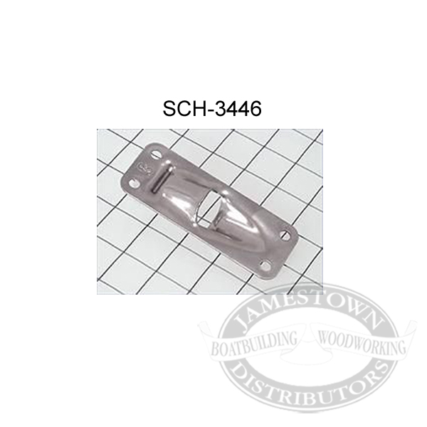
1) "Jogging" - For lack of a better term, would be where the device installed in the mast allows the halyard to get jogged out of the mast, where it continues down the mast. The device only jogs the line out, the final direction of the line is the same (roughly) as it was before entering the device. An exit plate like this has this effect:


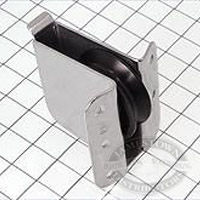
2) Turning the line out- In this scenario the exit device turns the line to a different final direction than its initial direction. The line enters at 0 degrees and leave at 90 degrees (for example). This is the type of device that is included with the CD internal halyard kit:


So here are my questions. Am, I missing something about the exit block sold by CD? Is there a way to use this to "Jog" the line out instead of turning it out? As I mentioned in my previous post when I installed the block in my mast I had to grind notches below the exit block to allow the line to head straight to the deck organizer. If I used the stock cutout I would not have been able to turn the line less than about 75 degrees (guessing). It's possible I have it installed wrong or the line threaded through it wrong.

I used this part from CD and I installed it just as it is oriented in this picture. The lines run down the back of the sheave and then threads between the sheave and the cross pin at the bottom and then out the mast.


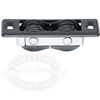
Another question, what is the purpose of a block like this:


Is this supposed to be used with 1 line so that it is jogged out of the mast and runs straight down or is this intended to be used for 2 lines that are coming from opposite directions?

Edited by - on
Go to Top of Page

MrKawfey
Navigator

Members Avatar

USA
124 Posts

Response Posted - 05/26/2013 :  09:39:09  Show Profile
Also, to comment on Alex's advice, if I my understanding of the CD exit block is correct and Tom were to install the CD exit block at shoulder height he would find there is no way to lead the line to the base of the mast.

Edited by - on
Go to Top of Page

Stinkpotter
Master Marine Consultant

Members Avatar

Djibouti
9014 Posts

Response Posted - 05/26/2013 :  10:02:15  Show Profile
I think you've got it all right, Chris... and I strongly suspect that double-sheave exit (one over the other), as you suggest, lets the line exit and then turn down, parallel to the mast. That would eliminate some drag compared to the "jog" fitting in your point #1.

Edited by - Stinkpotter on 05/26/2013 10:03:36
Go to Top of Page

tomh
1st Mate

Members Avatar

USA
83 Posts

Response Posted - 05/26/2013 :  10:26:48  Show Profile
Guys,

I did delay the project by about a week because I ordered a mast/step plate. The weather in Toledo turned out to be rainy so it was fortunate and an easy decision.

I'm now planning on being aboard Karma this Wednesday and Thursday to do the halyard project.

I also have a CD topping lift kit to install but I thought that the lift was secured to the top of the mast and controlled from the back of the boom? I never considered running the line down the mast. Is that a mistake? I would like to do it right the first time.


Edited by - on
Go to Top of Page

MrKawfey
Navigator

Members Avatar

USA
124 Posts

Response Posted - 05/26/2013 :  11:11:35  Show Profile
Tom, You have it right. The CD topping lift kit is adjusted at the boom end. For me, since I was already converting to internal halyards, adding a topping lift just meant buying a length of 1/4 rope, tying it to the boom end and running it over one of the sheaves in the masthead. Keep in mind, it sounds easy, but only because I had already mounted triple clutches on either side of the poptop, winches on the cabin top, deck organizers, the ball bearing replacement sheaves for rope in the masthead, and the double exit block on either side of the mast.

I think you could hear arguments both ways for which is better and quite frankly, I can't say there is any clear winner. As I mentioned earlier, the one benefit the we enjoy which would be hard to replicate any other way is the ability to pull our boom WAY high at the dock. What we do is hook up the pigtail from the backstay and then haul the topping lift until the pigtail is all the way up. This gets the boom out of the cockpit, but also, because the topping lift and the pigtail are both taut working against each other, the boom does not swing around. This also allows us to unclip the mainsheet from the boom end and clip it to the sternrail. All this clears out the cockpit nicely. We leave it stored like that when we leave the boat. It does look a little weird to walk down the dock and see all the horizontal booms and then one sticking up in the air like our boat is really excited to see us.

Edited by - on
Go to Top of Page

Stinkpotter
Master Marine Consultant

Members Avatar

Djibouti
9014 Posts

Response Posted - 05/26/2013 :  13:36:38  Show Profile
<blockquote id="quote"><font size="1" face="Verdana, Arial, Helvetica" id="quote">quote:<hr height="1" noshade id="quote"><i>Originally posted by MrKawfey</i>
<br />...then one sticking up in the air like our boat is really excited to see us.<hr height="1" noshade id="quote"></font id="quote"></blockquote id="quote">

Edited by - on
Go to Top of Page

MrKawfey
Navigator

Members Avatar

USA
124 Posts

Response Posted - 05/27/2013 :  19:30:23  Show Profile
I was up at the boat today and I thought I would snap a picture of one of my exit blocks. You can see how I had to notch the mast below the area where the line exits to get a fair lead to the deck organizer.


Like I said, if I had it to do again I would use an exit block like the double sheave harkin one in the picture above, exit it at about shoulder height (like Alex mentioned) and run it down to a turning block at the mast step.

Slightly different topic, but might help your project, whenever I bolt something new to the cabin top I use these things called barrel nuts. They allow you to install stuff without adding skull splitters to the inside of your ceiling:


They are stainless steel and I drill a small hole in the center of the Philips head cross so there is no issue with crevice corrosion. You can get them here:

http://www.jamestowndistributors.com/userportal/show_product.do?pid=1451& engine=msn& keyword=stainless_barrel_nut

The trick is to make sure you have exactly the right length screw.

Good luck with the project.

Edited by - on
Go to Top of Page

awetmore
Master Marine Consultant

Members Avatar

USA
1144 Posts

Response Posted - 05/27/2013 :  19:51:37  Show Profile
My Pearson uses mast exits like the SCH-3446 shown.

The other nice thing about having lines exit the mast farther up is that you can stagger the exit holes to avoid having a big weakened section concentrated in one location on the mast.

Edited by - on
Go to Top of Page

Lee Panza
Captain

Members Avatar

USA
465 Posts

Response Posted - 05/27/2013 :  22:21:08  Show Profile  Visit Lee Panza's Homepage
<blockquote id="quote"><font size="1" face="Verdana, Arial, Helvetica" id="quote">quote:<hr height="1" noshade id="quote"><i>Originally posted by MrKawfey</i>
<br />...5) If I were to do it over again I would use an exit plate higher up and run the lines to blocks attached to the mast base.
http://panza.smugmug.com/MYSAILBOAT/The-Boat-Renovation/Mast-Modifications/21650162_bHQXBG#!i=1743997219& k=Kb2MhxG
Check out this link, I wish I had seen this first...
<hr height="1" noshade id="quote"></font id="quote"></blockquote id="quote">

Chris, you shamed me into putting up a few more pix on my Smugmug site. I snapped a few today with my phone, showing what the base and the lower portion of my mast look like with the running rigging all installed. The CAD sketches might make more sense in conjunction with the photos, and vice-versa. This boat is very much a "work in progress" and there's a lot more to be done, but once the rigging controls were done I've found myself more inclined to sail it than to work on it.

The last image in today's set is the most relevant to this discussion of exit mechanisms. It compares to one of the CAD sketches where I laid out the heights of the exit plates:


The plates I used (Ronstan 6031) have an optimal deflection angle, which becomes evident by placing a dowel the size of the rope through the opening; with the dowel bearing on the top and the bottom of the plate you can see what angle the line would take. I installed one pair (port & stbd) at the optimal height (determined by the block at the base plate), and a second pair above and a third pair below the optimal height. I wanted to stagger them to avoid removing too much metal at that optimal height. This is an old spar, with a lot of screw holes from previous installations, so some of my own holes had to shift slightly to avoid them. BTW, the Ronstan exit plate has a tab on the inside of the mast that the line passes over; I bent them to lie flat against the inside of the mast to reduce friction and to avoid the chance of a slack line getting hooked around the side of the tabs.

Now that I'm playing with this arrangement the work is paying off. I sail on San Francisco Bay, where winds can vary from dead zero to 25 knots and better within a fraction of a mile, and it's really nice to be able to adjust the rig so extensively from the cockpit on the fly.

I hope this all will help someone who looks through the archives of this forum for help, as I did when I started my project.

Edited by - on
Go to Top of Page

MrKawfey
Navigator

Members Avatar

USA
124 Posts

Response Posted - 05/28/2013 :  10:14:10  Show Profile
Lee, Thanks for updating the pictures that is really helpful. One question I have, how difficult is it to raise your mainsail? Can you hoist it all the way to the top without using the winch? Are you still using the plastic slugs in the sail track?

Edited by - on
Go to Top of Page

Lee Panza
Captain

Members Avatar

USA
465 Posts

Response Posted - 05/28/2013 :  20:13:25  Show Profile  Visit Lee Panza's Homepage
<blockquote id="quote"><font size="1" face="Verdana, Arial, Helvetica" id="quote">quote:<hr height="1" noshade id="quote"><i>Originally posted by MrKawfey</i>
<br />...One question I have, how difficult is it to raise your mainsail? Can you hoist it all the way to the top without using the winch? Are you still using the plastic slugs in the sail track?
<hr height="1" noshade id="quote"></font id="quote"></blockquote id="quote">

I'm still using the old, blown-out mainsail that came with the boat, and the worn nylon slugs that were seized onto it. That having been said, the degree of difficulty I experience in hoisting it is entirely dependent upon the wind. When it's light, or when I can head up into a moderate breeze, I can hoist the main all the way to the truck without the winch. On the other hand, if I can't get the boat to stay in irons it can be tough to get it up all the way (watch it, punsters). This, by the way, is without any lubricant (watch it!) like Sailcoat in the track, which is often recommended to make the slugs slide more easily. From what I've read this is fairly common experience. One thing you might check is how much play there is in the seizings holding the slugs to the luff: if they can move up and down, instead of being held parallel to the luff, they'll be more likely to bind.

Edited by - on
Go to Top of Page

pastmember
Master Marine Consultant

Members Avatar

2402 Posts

Response Posted - 05/29/2013 :  19:45:14  Show Profile
You do release your mainsheet and vang when raising the main... right?

Edited by - on
Go to Top of Page

tomh
1st Mate

Members Avatar

USA
83 Posts

Response Posted - 05/29/2013 :  23:28:15  Show Profile
I started the installation yesterday and it is turning out to be a slightly bigger job than I thought (aren't they all?).

After I pulled the wires out of the mast, I decided to replace them.The past 35 years have not been kind to them. The lights need to be replaced also.

I installed 3/4 pvc pipe for the wiring. Is it OK to run the radio wire through the same pvc pipe or would there be a lot of interference?

There also seems to be foam rubber in the mast around the compression post.

Does anyone have any suggestions on how to get this out? My best guess is to get another 30 ft section of pvc pipe and use it like a ramrod to force it out.


Edited by - on
Go to Top of Page

awetmore
Master Marine Consultant

Members Avatar

USA
1144 Posts

Response Posted - 05/30/2013 :  07:11:20  Show Profile
My Pearson has the VHF and lighting wires running through the same piece of PVC inside of the mast. It seems to work just fine.

I have to say that I don't use my masthead light and my radio at the same time very frequently.

Edited by - on
Go to Top of Page

tomh
1st Mate

Members Avatar

USA
83 Posts

Response Posted - 06/01/2013 :  13:50:34  Show Profile
I finished running the lines last thursday but decided to order a new wire harness,radio cable and install a mast deck plate before I buttoned up the project.

Another problem....The antenna plug in the deck interferes slightly with the deck plate mounting.

Any suggestions on moving the plug or other options?

Edited by - on
Go to Top of Page
  Previous Topic Topic Next Topic  
 New Topic  Topic Locked
 Printer Friendly
Jump To:
Association Forum © since 1999 Catalina Capri 25s International Association Go To Top Of Page
Powered By: Snitz Forums 2000 Version 3.4.06
Notice: The advice given on this site is based upon individual or quoted experience, yours may differ.
The Officers, Staff and members of this site only provide information based upon the concept that anyone utilizing this information does so at their own risk and holds harmless all contributors to this site.