Notice:
The advice given on this site is based upon individual or quoted experience, yours may differ.
The Officers, Staff and members of this site only provide information based upon the concept that anyone utilizing this information does so at their own risk and holds harmless all contributors to this site.
<center></center> My boat has a Raymarine ST4000+ autopilot. As you can see in the above picture, its control panel is mounted in the starboard coaming, aft of the cubby hole storage. I would like to get behind it to install a SeaTalk cable to connect with my ST30 depth gauge which is on the forward bulkhead, where passengers often obscure my view. That way I can view the depth on the ST4000+, which is closer to the wheel. (This will also allow me to interface both with a chart plotter package that I am assembling.)
What is the best way to get back there? It looks like I have to remove the aft bulkhead behind the sleeping area, and try to get my (no longer skinny) body back in the lazarette area far enough to reach around and up behind the LPG locker. Hopefully the optional cover is not installed over the back of the ST4000, so I can feel my way to the SeaTalk receptacle and plug in the cable. Otherwise I'll have to remove the thumb nuts (hopefully without dropping and losing them) and pull the control panel forward into the cockpit to access the back.
My question for those of you who may have hunted around back there before is whether I'm missing some easier way to access it. For instance, is it possible to remove the LPG equipment, pull out the liner from that locker, and get up behind the coaming by reaching up behind the locker? Right now I have a sawhorse sitting on the locker to support the dropped mast, so I can't even open the locker to look inside.
Rick S., Swarthmore, PA PO of Take Five, 1998 Catalina 250WK #348 (relocated to Baltimore's Inner Harbor) New owner of 2001 Catalina 34MkII #1535 Breakin' Away (at Rock Hall Landing Marina)
It'll be reasonably easy to get to after you remove the aft-bulkhead as Steve said. It's not a painful process, just a bit tedious. A battery powered drill with a #2 Phillips's head will speed the process. It's easier if you remove the mattresses, but you can just slide them forward six inches or so, and you'll have room to work.
I just removed the battery compartment cover in order to install a second set of gudgeons. The cover is easier off than back on. There's a bit of a problem securing the port side of the cover. Better to remove the matress first. . . one less obstacle to overcome in the process.
Thanks for the advice. I am less worried about taking the bulkhead off than I am about contorting my body to reach up behind the coaming. Fortunately, all upholstery was removed from the boat prior to haulout, so the mattress will not be a problem. The battery was removed also, so that's out of the way.
However, removing the bulkhead does have a few issues. First, it looks like I need to remove the small port bulkhead that forms a small storage area on the port side of the berth. Is that correct? That looks very straightforward.
Perhaps less straightforward is the fact that my 120v shore power panel and charger are both mounted on the starboard side of the aft bulkhead. I need to check how much slack there is in the wiring, but there's a good chance I'll have to disconnect all the wires to get the bulkhead out far enough to get back into the aft area. If there's enough slack then maybe it will be easier.
Have any of you actually reached back there? It must be reachable, since the original installer had to do it. From everything I can tell, the boat was originally delivered with tiller steering (that's why there are compass and depth on the cabin bulkhead) and the wheel and autopilot were retrofitted about 2 years after original purchase (since the ST4000+ manual has a 2000 copyright date).
I had an Autopilot in the same spot. I have removed mine but the process you describe to get back there is right. Yes, there are contortions involved but they are do-able. It is easiest to remove the unit and then do your cabling. There are a lot of connection points on that control head and it is tough to get the right one, especially if the one you want is on the top.
After removing the aft bulkhead a few times I decided to cut it on the port side of the battery door. Now I don't mess with my electrical panels or the port storage area when I need to get back there. I just remove the starboard side. Easy project to do.
Every now and then I need to remove the port side of the aft bulkhead and that is where my electric panels are installed. To make that easier I use marine-grade plugs to connect the AC panel wires to the boat AC power and the AC shore-power source. Just unplug them and the panel is ready to remove.
Finally, while you have the saw out, cut the V-berth cover down the middle and piano-hinge it so you don't have to remove both cushions and the whole cover to get down there.
Ah, your newer boats are a bit different than mine. I have no electrical connections on the bulkhead, except for a 12 VDC connector the PO put in, which I've since rewired so it's easy to disconnect.
I'm a big guy, and I can get all the way inside the rear compartment, but not with the bulkhead in place. With a bit of wriggling, I can get nearly seated upright leaning on the inside of the transom/starboard side joint. My autopilot, solar panel, and external DC connections are all in the same general area as your autopilot, but about a foot lower. I've either installed them new, or rewired all of them from inside the compartment.
Rita on the other hand, can crawl through the battery door, that's how we hooked up our electric bilge pump's overboard connection. She was able to wiggle right over the top of the single battery we used to have, not so sure she could do it over the dual battery setup now.
I've always liked Randy's solution to his bulkhead wiring problem, just never saw it as necessary for our boat, but maybe a good solution for yours?
FYI, on the new models, the batter is in a raised 'moat' that makes it nearly impossible to remove the battery! The 'moat' also would make getting to the underside of the aft combings almost impossible too!
I split our bulkhead like Randy (only on the Stbd side, port makes much better sense!) and I cut down the 'Moat' so that the front is only about 2" high making it easy to get the battery out.
David - From the factory, my boat is not that much different than yours. I do not believe that the shore power system was included on any of these boats during that period - it was a dealer install, which is why you find the connector in so many different places on different boats.
I wish I could make all the mods that Randy has suggested, but previous owners' mods unfortunately make it impossible. For instance, I'd LOVE to split my V-berth cover in half like Randy did. Only problem is that it is already split in half THE OTHER WAY . This makes no sense, as it still requires me to remove both V-berth cushions to get into that area.
Also, my 120v panel, charger, and a GFCI outlet were all installed on the STARBOARD side of the bulhkead. So splitting it in half does not gain much unless I want to access the port side of that compartment. And I can't really move them because there was a large cutaway for the 120v panel.
The marine-grade plugs are a good idea. I'll have to see how much slack there is in the wires, and how often I go back there. It may be worth the expense - but those Marinco connectors set you back pretty well!
Off topic:
While I express a little frustration with a couple of these mods made by others, overall the mods that were made to my boat were much better done that some of the other C250s that I saw when shopping. The absolute worst one was the 120v/12v panel that was installed in the front of the galley cabinet - WITH EXPOSED 120v WIRES AND TERMINALS RIGHT INSIDE THE DOOR UNDER THE SINK. Plus, every single 12v wire had to be spliced at the original panel location so that the wires could be redirected down to the galley cabinet.
And then there was the other C250 with the "window" that was cut out for the aft berth. It was a cheap clear circular inspection port, and <1" from the cockpit floor. Having it so close to the floor compromised the strength so that the floor flexed a little too much when you stepped on it, causing the seal to break (no matter how much caulk you put there). This, plus the splashing from the cockpit floor onto the port whenever it rained caused water to leak badly there, with no clear way to fix it.
All of these things make me think two or three times before ever cutting into fiberglas.
I tried to remove the aft bulkhead today, but was not successful. Right next to the bilge pump hose that runs along the port side, there is an even larger hose from the marine head to the holding tank. (I discovered this AFTER removing all the screws.) That larger hose has a joiner just forward of the bulkhead which prevents it from being removed. The only way to remove the bulkhead would be to disconnect and disassemble the holding tank hose, which I am not willing to do because of the stinky mess it will make.
I am going to go back tomorrow and see if I can crawl through the battery opening far enough to reach behind the autopilot. I'll need to work my arms through several electric wires and the Edson steering cables. I could get my head in far enough to see that the back of the Autopilot is uncovered, so if I can reach back there I should be able to plug in the Seatalk cable without having to remove the control panel. I was not comfortable going back there by myself, so I'll take the Admiral with me to pull on my feet if I get stuck.
You wouldn't catch me crawling through that opening. Any issues and they would have to cut the boat up to get me out (and I only weigh 190lbs)
Can you ease the holding tank forwards enough to get the bulkhead out.
Considering you have that hose there, I would definitely cut the bulkhead as shown above.
Sadly I think that the manufacturer puts things together for the ease of manufacture and not of service.
eg. Our Battery moat, no way could I get the battery over the top of it. So I cut it with the batteries in place. I'm guessing that they put the battery in place before lowering the cockpit, could be wrong.
Your message's timing was impeccable. After spending a couple hours with fish tape routing the SeaTalk cable from the depth finder back into the rear compartment, I called my wife to come down to the boat for the part that I was uncomfortable doing without someone there to help if I got into trouble. While I waited for her to arrive, I decided to check my messages and saw your concerns. Your message made me really doubt what I was planning, since I also weight 190. Just then I heard, "Hi, honey, I'm here!"
Not wanting to send her away after driving all the way down there for me, I decided to give it a try. Before she arrived I had put a drop light back there to provide light and some heat, and a couple of boat cushions behind and in front of the bulkhead to minimize the trauma to my back. (Note that the mattress is at home for winter storage.) It turned out to be a piece of cake. Less than 2 minutes and I had plugged in the cable, attached the ferrite choke, and was out of there. It was definitely a tight fit, but no big deal.
Note that my (single) battery had been removed for storage on trickle during the winter. There is no way I would have gotten back there with the battery in place. I don't really understand the problem you had with your battery. My "moat" is a tight fit for a type 24 battery box, but the pan is only a couple of inches high. It's awkward getting the battery out due to its weight and limited headroom in the aft berth, but it came out with no problem for me. In fact, I've removed it a few times for various reasons.
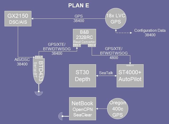
I might have mentioned it elsewhere, but connecting depth with autopilot is part of a much larger project. In addition to getting the depth readings to display closer to the helm on the autopilot panel, I am going to translate the SeaTalk to NMEA and integrate it with a new VHF/DSC/AIS receiver (Standard Horizon GX2150, still on order) and send it all via Bluetooth to a netbook for display on OpenCPN and/or SeaClear:
I'll be sure to let you all know how it goes as the equipment arrives and is tested. To keep costs down, I've tried to avoid buying an expensive marine multiplexer, opting instead to get a baud rate converter, Raymarine's NMEA converter, and a serial-Bluetooth adapter.
I am now confused... wiring, sawing, etc. is easy.... but the electrical engineering has me confused. Your autopilot must not have the pilot (course) controller like the new X-5. On the x-5 the control head connects with sea Talk to the controller, The tridata ST60, and the A50D Chartploter/Fishfinder all link to a the controller. No bluetooth, no NMEA... no computer...
So I assume that the ST4000 does not have a separate controller...
The above is the plan for my system, and it will crosstalk...
If you like the electronics, look at Control4 for your home...
I am not familiar with those models, but I am certain that if you have an all-Raymarine system, then SeaTalk gives you plug-and-play capability.
My autopilot is able to follow a track, but it has to get the track bearing, XTE, SOG, GPS coordinates, etc. from an external GPS/chartplotter. In my plan I will send that from an external computer/GPS via NMEA/Bluetooth. In your system, it sounds like your X-5 gets that information from the A50D via SeaTalk. It's just another way of doing the same thing.
I had originally purchased a GPSmap 640 to do all of this, but ultimately decided that my Netbook (which had been sitting around gathering dust) would be a better option because it has a larger, amazingly bright display that can be read in full daylight. Unlike the GPSmap 640, I can also do it wirelessly, so I can have the Netbook in the cockpit or in the cabin depending on weather conditions. And I wanted the flexibility of using OpenCPN, SeaClear, or one of the other commercially available chart plotter packages. These are my own choices, and it's fine if others want more of a turn-key system.
FYI, the schematic I showed above is outdated and will not work as I had hoped. A more updated description is in the link and schematic shown here:
Notice: The advice given on this site is based upon individual or quoted experience, yours may differ. The Officers, Staff and members of this site only provide information based upon the concept that anyone utilizing this information does so at their own risk and holds harmless all contributors to this site.