|
|
|
|
|
|
|
|
|
|
|
|
|
|
|
|
|
|
|
|
|
|
|
|
|
|
|
|
|
|
|
|
|
|
|
|
|
|
|
|
|
|
|
|
|
|
|
|
|

 |
Installing the Pull-Pull Steering System |
- In-Line Conduit Greasers, p/n 918-250, 2 ea., p. 21
- Conduit Lubricant, p/n 827-3, p. 2
- Stainless Thimbles, p/n 643-187, p. 13, 2 ea.
- SS pan head bolts, 3/8-16x2, 6 ea., not in catalog
Instillation of the pull-pull steering system.
by Doug Andrijasevich., C250wb, San Francisco Bay area on 10/31/02
The Edson catalog can be found on line at http://www.edsonintl.com/
The kit arrived and consisted of the following components:
1. Chain and Wire Rope Kit, p/n 775-2S15B11, p. 12
2. Transom bracket, p/n B-831, not shown in catalog
3. Pedestal bracket, p/n C-708, looks like #868-2 on p. 21
4. Conduit, p/n 853-250 about 2-5 ft pieces, p. 20
5. End fitting 854-250, 4 ea., p. 20
6. Galvanized wire rope clamps, 4 ea., p/n 665-187, p. 13
7. Take-up eye, 2 ea., p/n 618-312, p. 13 & p. 19. These were attached to
a short rod that fits through the tiller arm and is not shown in the catalog.
8. Aluminum Pedestal Bolts, 4 ea. p/n 646-4hex with nuts
Total cost $491 plus shipping ($18.50.)
 |
Parts that should also have been included:
|
| The first step is to remove the pin holding the tiller arm to the rudder housing. This will save you a trip off the boat later, unless you need the exercise. | 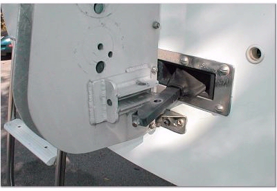 |
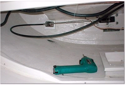 |
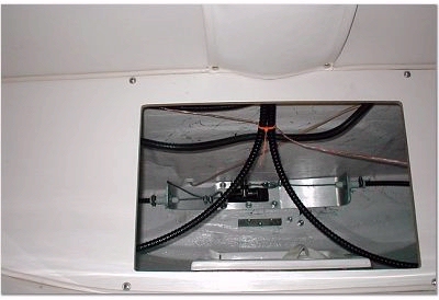
I cleaned everything out from the aft berth and then removed the aft bulkhead. The present cable is routed through a bronze housing on the starboard side and is connected to the tiller arm by a pin. All of these parts need to be disconnected. |
If you didn’t remove the pin at the rudder housing first, you will have to climb out and do it now. (I speak from experience.) If you notice in the picture there is a small pile of black rubber under the bronze fitting. This is a result of the locking nuts that hold the rubber grommet in place being loose, mine is now trash. (A lot of the bolts I checked were loose or finger tight, so check everything while you are there.)
Next you need to go on top and disassemble the pedestal. First remove the wheel, which I didn’t and had to fight it for a while. There are 4 screws holding the compass in place and are located on top of the compass, they are the larger ones. Next you need to disconnect the power to the compass light and set the compass aside. Inside there are 4 screws that attach the spacer housing and the pedestal guard housing to the pedestal. My parts were also attached with some sort of adhesive and needed a little help to come apart.
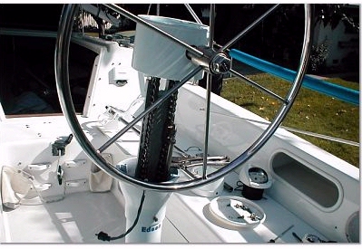
I pulled the internal mechanism up and held it in place with a pair of vice grips while I disassembled the plug for the power to the compass light so it would fit through the hole in the aluminum bracket and removed the clamp holding the power wire in place. (Did you ever wonder what that bolt with the nylanut on the back of the pedestal did?) Now everything from the tiller arm up will come out.
I first attempted to fit the new bracket to the transom, its marked port and starboard so I knew what went where. The bolt pattern in the bracket was machined to match the bolt pattern in the SS flashing holding the rubber boot around the tiller arm. One big problem, the flashing only required the bolts to hold it in place, so they were hand drilled, some a little to the left, some a little to the right, some a little to the top, & some a little to the bottom. So the new bracket needed work to match up
 |
This took about 2 hours to in-large the holes and grind off enough material from the top side to fit because the original slot was about 1/8 in. higher than it should have been. This is when I found out that the original bolts were too short for the new bracket. I spent 2 hours on a Sunday morning looking for 6 ea, SS 3/8-16x” pan head machine screws; I had to settle for hex head. 1 ľ” bolts would have also worked. |
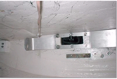
| Now it was time to mount the pedestal bracket from the bottom, but first several things need to be done. | 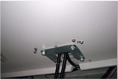 |
The original hole was not big enough or in the right place so I used a 3 ľ” hole saw to cut a new hole which overlapped the original hole a little bit. The kit included 4 new aluminum bolts for the base of the pedestal and they were about 2” longer than needed. I chose to measure and cut before installing them, which made that job a lot easer. I had the same problem here with the bolt pattern; one was so far out that I had to make the hole a slot to fit. From the topside, after reinstalling the wire bracket, I turned the wheel shaft until the key way was on top and locked it in place with the break. I located the middle of the chain and dropped the cable and chain down the pedestal leaving equal lengths on each side. Using a couple of c-clams and squares I clamped the rudder housing perpendicular to the stern. From the bottom, I greased and inserted each cable into its conduit, which had been attached to the pedestal bracket. The last step was to bolt the pedestal bracket in place.
Now comes the hardest part of the job because you have to crawl all the way to the back and work in very small space. The take-up eye assembly is attached to the rudder arm. This has several holes in it, I reused the one at the end to keep the same ratio as before. If you use one of the closer holes, you will not have to turn the wheel as far for lock to lock but it will require more effort. The conduits can now be attached to the bracket. Be sure not to cross the cables in the pedestal or the conduits while routing them. The holes for the conduits in the bracket are offset to rout the starboard cable to the bottom of the rudder arm and the port side to the top of the arm. Edson’s catalog shows the cable going through the take up eye without a thimble but I didn’t like the sharp angle and stress this would cause so I added a thimble here, about $1.50 at West Marine. Run the cables through the eyes and clamp them, get the clamps as close to the eyes as you can or they may limit the travel length of the rudder arm. Adjust the cable tension with the take up eyes.
 |
You are now ready to put everything back together and go sailing. |
| You will have these left over parts. | 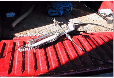 |