Notice:
The advice given on this site is based upon individual or quoted experience, yours may differ.
The Officers, Staff and members of this site only provide information based upon the concept that anyone utilizing this information does so at their own risk and holds harmless all contributors to this site.
<blockquote id="quote"><font size="1" face="Verdana, Arial, Helvetica" id="quote">quote:<hr height="1" noshade id="quote"><i>Originally posted by OLarryR</i> <br />If your Catalina is like mine (wire configuration) and you want to try and reuse the old wiring (which is easiest solution but I did not realize the wire was not encapsulated in the cabin liner until after I strung new wires), then check in the bilge for the casing that encloses the mast wire.
I used the opportunity when rewiring to install a new circuit switch panel. I placed it just below the sink where it is accessible from the cockpit. The old panel is still working as well but it is under the steps and a pain to get to when putting on the nav lights. <hr height="1" noshade id="quote"></font id="quote"></blockquote id="quote">
Thanks for the heads up Larry, I need to rewire mast circuits inside my boat, I would not have looked i the bilge, that helps a lot. I already have the new Nav Light panel installed under my sink. Last season it developed a short to ground in the mast light circuits so I cut power to it at the panel under the steps. On the rewire I may make it autonomous rather than in series. Series was just the easy way to install it. I have a photos of that install on my site. I needed to move a 110 volt wire before I cut out the hole for the panel.
I also installed a new ground buss bar.
The panel I picked has a 12 volt socket in the bottom right corner for a hand held flood or Davis anchor/cockpit light, or what ever. And I kinda like the little battery tester too. Like you said Larry it was about getting the Nav light circuits where a guest could stand a chance of success in finding them!
I replaced the electrical deck connection on our boat this past spring and hope to replace the wiring this coming year if time and budget allow. I second Larry's observations above. On the '89s at least, Catalina did not seal the wiring into the deck. Instead the wiring drops vertically from the deck connector and then horizontally for ~3" inside the angled "molding" between the interior ceiling and the deck to the mast post and then down to the bilge. I don't know if new wiring can be successfully pulled its entire length through this route but it's worth a try. By ensuring slack at the base of the mast post I was able to pull one wire at a time 3-4" up through the deck without a great deal of difficulty to allow me to cut back the corroded sections and then install a new deck plug. Once attached I was then also able to pull the wires back down from the bilge area until just lightly snug to allow the deck plug to seat well.
Good luck and let us know how things work out. BTW....I downed many an oyster in the Kemah/Seabrook area 20+ years ago; an interesting place.
I thought I read somewhere here on this forum that some of the trim could be removed from around the mast post so you could access some of the screws that hold the bulkhead in place. I may try removing that trim piece if I can't get the wire to pull through. By doing this maybe it's possible to grab a portion of the wire to help pull it down/up.
Before I try that I think I may buy some of that wire lube at Home Depot that electricians use so they can pull wire through long runs of electrical conduit. Lube up the new wire with the wire lube and I'll bet it will slide down through the passageway with little resistance. I already have a wire puller(snake). If not, I may have one big mess on my hands or maybe the lube will seal some of the wood along the mast post so water can't penetrate and rot it out!
You have the best photos ! I think soon you will have photographed every inch of the boat ! The negative bus bar - What did you do - Climb into the bilge from the cockpit ? If i did that, I would be afraid I would get stuck there and no one would find my remains till Spring ! By the way, when I started the electrical work, I located my new switch panel under the sink based on your suggestion. Only thing is that the contacts come a bit close to the sink bowl. I wanted to ensure there was no contact made or any spark, etc jumping the gap, so I used a thick insulation tape, cut strips and adhered them to the underside of the sink. There is still clearance but it is a bit close and the tape at least makes me feel better even if there is no concern.
Gerry & Gary: Something you may also want to consider..well I guess Gerry already used the old wire which is great ! Another option which really is fairly easy is to not try and re-use the old wire but install a new one. There are some benefits besides new versus old. The biggest issue to overcome is drilling a new hole but that can be done thru the deck connector hole so no leak paths. I removed the deck connector and then using a long drill bit (~ 10" long) from Home Depot, I drilled at angle forward thru the liner. I was hoping for it to come out in front of the cabin bulkhead in the area where the porta-potti is located. I then took a look and did not see the hole...but I was sure i drilled through the liner ? So...passed the drill thru the liner again and wiggled it to make the hole a bit larger - definitely into the below deck space. Took another look...no hole ! Then I looked more carefully and noticed a small slit in the small rubber trim that lines the bulkhead to cabin top joint - That was where the hole came out - into the porta potti area but right at the bulkhead/top joint ! Fine !
I used Anchor 5 wire mast wiring and strung it back to the switch panel by attaching it up close to the bulkhead/cabin top joint and down to the shelf behind the porta-potti. Drilled a hole thu the shelf and then snaked it back to the switch panel.
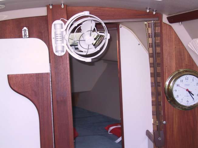
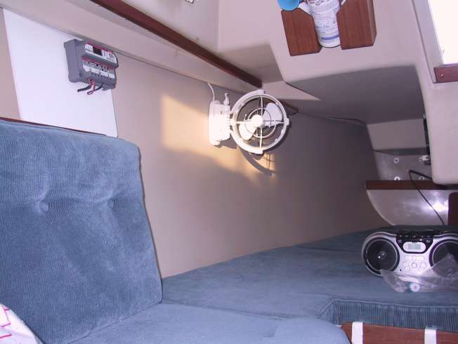
Since i used 5 wire mast wire and only needed 4 wires (3 positives and a negative), I used the 5th wire inside the cabin for a fan I mounted at the top of the mast column in the main column. The wire is conveninet to that location to utilize a fan there. The negative i spliced into for completing the circuit. I then ran a separate wire to another fan located in the quarterberth area and hooked both fans to same switch. The fans are multi-directional, 3 speeds, have a timer for keeping on for a set number of hrs or continuously.
Photo details of the fan(s) and switch panel on my website.
I angled the drill bit forward (parallel to the bow/stern just to punch thru into the porta-potti area. I just wanted to make sure it entered the right area and angled forward and not to the sides puts the hole as forward as possible. As it is, it just made it into the porta-potti area.
I can't remember what size long drill bit I bought but I remember I bought two sizes to ensure I had an adequate size to get the wire through it.
Here is the link for where I bought the Anchor brand mast wire:
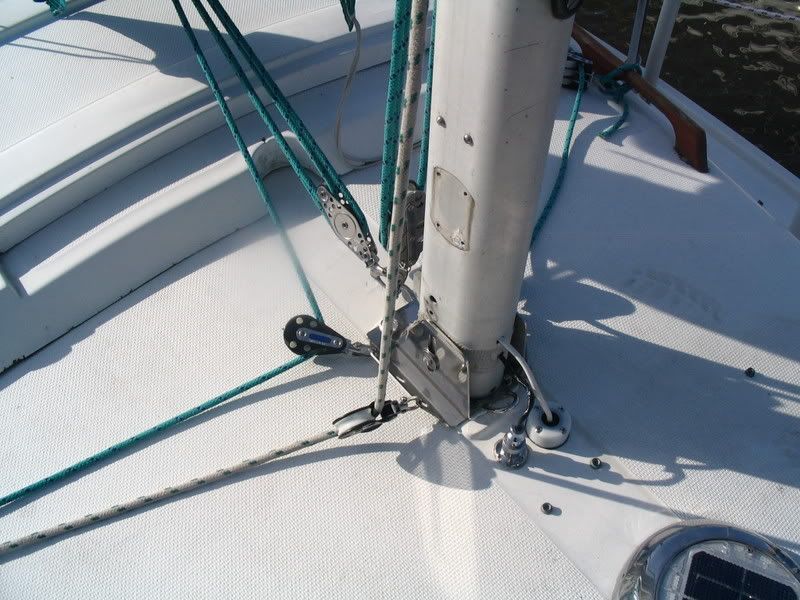
One of the things about the 89 that I consider a design flaw is the exit block heights for the internal halyards, they cause a tripping danger at the mast. The halyards also do not lead fair to the deck organizers. I am a big believer in halyard plates for a multitude of reasons, (I think standing turning blocks on the deck like so many of the older boats have are an even worse design flaw), so when replacing a deck plug I would absolutely make sure I left room for a halyard plate at the base of the mast. (Do you sense a picture coming?)
If you go to this photo and download it full res you can zoom in and see the change in the halyard angle and see the deck plug location. The photo is part of my bimini series, so it is at the end of the third page. I need to take more photos!I did not need to change my deck plug location but it was close and I assume no two boats are exactly alike. http://gallery.mac.com/fhopper/
Well I started working on my wiring today. I decided to tackle the wiring connection at the deck connector. I was able to pull the wire out far enough to re-connect the wires to the connector. It was very tight in the hole. I had three red and one yellow wire after I removed the PO's wiring splice. Now I just need to figure out which wire goes to which pin. I didn't have the owners manual with me so I quit after I got the wires re-attached.
I asked the question before but Larry's link didn't tell me what size wire is used from the switch panel to the deck connector. Does anyone have that info handy? I think if I switch to the flat four wire cable I will be able to pull the new wire up through the mast post. May have to enlarge the hole just below the deck connector though.
I am almost positive I used 14 gage wire from the panel to the deck connector. West Marine has a 12 Volt wire gage chart in their catalog. Inorder to figure out the recommended gage, you need to determine the approximate load (mast lights on at one time)and length of wire needed roundtrip between the load and the panel. It is a very long length to the top of the mast from the switch panel. It's about 30 feet one way to the top and then there is the cabin wiring which is a circuitous route back to the panel - perhaps another 20 ft. So that is about 50 feet X 2 (roundtrip) = 100ft.
By the way, I took a look at that link I provided earlier for the Ancor brand Mast wire. It did not come up with the Anchor brand wire. (Maybe the vendor stopped carrying it?)
In stead of messing with the bit of wire sticking out of the deck, I installed deck connecters and ran new wire from there both up the mast and back to the panel for both the lights and radio. It worked out great. P.S., I snipped the old wires as far down as possible and filled the gap in with resin. Cheers.
Well in attempt to get my boat ready for splash, I noticed the lights not working well on the mast. I checked out the wiring coming from the deck plug and was shocked. The original wires were in poor condition. I tried to extend the wiring so I can add the wiring to the into the deck plug, but that didn't work well.
I decided that its better to pull the wires, or replace. I have attached a few pictures below. I have a 1978 Catalina. I a removed the post and noticed no wiring in the post, I pushed the bulkhead support forward and noticed no wiring there as well. It may be better to drill a hole to the head, and feed the wiring down the post -- is it hollow -- and continue to feed the wiring back under the dinette seats to the panel. If I am going through all this work, I may as well make it a 4 wire set rather than remain it as three.
I noticed people suggesting 14 gauge wire. Any recs for type of wire? Radio Shack, CD? Looks like I shan't be splashing this weekend.
Never enough wire. Notice the orange wire down to nothing, and notice the lousy soldering job I did on the other two wires.
I pushed the Post aside to determine if wires traversed through it. Nada.
Top of cabin from the inside. Right is the head, left is the dinette area. No wiring or cutout channel for the wires. The wires in the background is for the head light. I suspect that on 1978 the wires were sandwiched in; designers figured there would be no need to work on wires for future projects.
Your advice is appreciated. Has anyone messed with this situation on a 1978? Wiring Recs? 14? vendor?
well well well,, Here is the info (see below) on the CD site regarding wiring and the placement of the wires on earlier boats:
"Fourplex wire is often used to replace the electrical run from the deck at the base of the mast aft to the electrical panel. In early boats (through the mid 80's) the wires were run within the thickness of the deck. There was no conduit and you have no access to it.
The four 16 gauge conductors, enclosed in a flat, white casing are a clean and unobtrusive way to replace the existing damaged or corroded circuit. It is also the correct choice for upgrading a mast originally equipped with only an anchor light or perhaps a steaming light. Simply lead this cable inside the boat, tucked in neatly into the top corner, forward of the main bulkhead. On a Catalina 22 it hides nicely just forward of the privacy curtain track. It provides all the circuits you need for a deck light, steaming light, and masthead anchor light.
Our marine grade wire is tinned along it's entire length. Tinned wire prevents corrosion from creeping up and throughout the wire, Corrosion compromises the ability of the wire to carry the electrical load and causes a major voltage drop at the far end of the conductor.
In addition, our marine grade wire is both larger and has finer strands than automotive wire. Automotive is up to 12% smaller than marine. Marine wire lasts longer, is easier to route, and carries more electrical current than automotive wire. Sold per foot. "
This is absolutely one case (one of the exceptions) where "marine grade" is important. Do not buy the wire at Radio Shack or any other non-marine source, and be sure it's tinned (all strands look silver).
Your wire runs between the deck and the overhead liner--as CD says, where there's nothing you can do about it. So fuggetaboutit. Their four-coductor cable is an ideal replacement. WM has it too.
Wow ! This is an old posting thread with a new spin to it. Anchor used to make a "Mast Wire" that had 4 or 5 wires in it. I am not sure if they sell it any longer. There were better prices on wire and better selection via a number of boat mail-order companies versus WM, though WM is definitely convenient. I still have the websites for the mail-order places and it is just a case of seeing what they now sell. You could also do a Search on Anchor wiring to see if they still sell their "Mast Wire". http://bestboatwire.com/catalog/default.php?cPath=53
I just checked the two websites I listed and the best Boat Wire website indicates they are temporarily OOC until they find another distributer. The Genuine Dealz website is still up and running and they do sell the Anchor mast Wire. Here is the direct link to it:
Thanks for the head's up. Yeah, I learned a great deal about my boat today as a result of looking for wires. I am going to replace the wiring and run it to the panel. The old wires are shot.
The Ancor wiring looks like a great solution because I can use the 4th wire for a deck light.
According to the <i>Catalina 25 Owner's Manual</i>, the anchor light and the bow light are GE-90 lamps, each requiring 0.58A. The orange and white wires Catalina originally installed were #14 AWG wire. According to Don Casey's <i>Sailboat Electrics Simplified</i>, #14 AWG wire can carry 1A up to 120 feet with no more than a 3% loss.
I'd estimate the distance from the electrical panel to the cabin top approximately 12 feet, and the length of the mast is between 29 and 31 feet, so the wire run is about 40-45 feet.
On the way back, the green ground wire, which is speced by Catalina as #10 AWG wire, must carry 2 x .58A or 1.16A. 2A can go up to 60 feet in #14 AWG wire with only a 3% drop.
Because 1/2 of the voltage drop takes place on the way out to the load, and 1/2 drops on the way back, you could be right at the hairy edge using #14AWG for the green ground on the way back.
Long story short, if your four wire cable is 4 by #14 AWG, if you use the fourth wire in parallel with the ground wire, you should have enough ampacity to light both the running and anchor lights at full brightness.
If, however, you use the fourth wire for another function, such as a fan or spreader lights, then you risk that your ground wire is too small to carry the extra load. For example, if you add 2 more amps, you will see a higher than acceptable voltage drop at the lights.
For example, a 5% loss at 12.6V is about 0.63V or 11.97V at the lights. This is not bad.
If your battery discharges overnight down to 12.2V, then a 5% drop would be 0.61V, or 11.6V. This is quite a low voltage and may be too low to operate your anchor light at full brightness.
Edit --> You could also add a #10 AWG ground wire alongside the 4-wire bundle, and you'd have plenty of ampacity for other circuits.
When you have a repair to make, what makes it uplifting is it also provides the opportunity for an improvement. So, using the extra wire for a potential deck light sounds like a great idea. On the '89, there were 4 wires - Anchor light, steaming light, deck light and the negative return wire. I used the 5 wire mast light because I remember having the extra wire and I eventually hooked that up to a fan that I attached to the top of the mast column in the cabin. I used the 14 gage mast wire and i also lowered the amp load going with an LED Anchor light. My thought was that it would be rare that I would ever have the steaming light and the fan on at same time and the deck light I generally only use if I come back to the dock at night-time and then only when putting the main sail cover, etc on. Then I turn it off. The two most likely lights that could be left on for a time would be the anchor light and fan. But the fan amps at low and medium speed are below an amp and I would only use those fan speeds. The nchor LED has negligible amp load. (My other fan in the quarterberth is run off of separate wires.)
When you have a repair to make, what makes it uplifting is it also provides the opportunity for an improvement. So, using the extra wire for a potential deck light sounds like a great idea. On the '89, there were 4 wires - Anchor light, steaming light, deck light and the negative return wire. I used the 5 wire mast wire because I remember having the extra wire and I eventually hooked that up to a fan that I attached to the top of the mast column in the cabin. I used the 14 gage mast wire and i also lowered the amp load going with an LED Anchor light. My thought was that it would be rare that I would ever have the steaming light and the fan on at same time and the deck light I generally only use if I come back to the dock at night-time and then only when putting the main sail cover, etc on. Then I turn it off. The two most likely lights that could be left on for a time would be the anchor light and fan. But the fan amps at low and medium speed are below an amp and I would only use those fan speeds. The nchor LED has negligible amp load. (My other fan in the quarterberth is run off of separate wires.)
Bruce, your point is well taken, but there should be no point in time where you're burning the steaming light and a deck light--the deck light will greatly diminish the helmsman's night vision. That's for being at anchor or in the slip, bundling the sails or whatever. Likewise, the anchor light is not for use under way. So at any point in time, it's steaming light only, or anchor and deck lights (when the steaming light is of no use).
I stopped this project ( mast/steaming/deck and rewire ) to wait for technology to catch up. I've been using a battery operated LED light up the jib halyard/for-stay for an anchor light. I had tried to push the bulkhead forward to inspect the wiring to the mast. My deck connection is mostly working, you have to wiggle it.
I am watching prices for the LED lights to come down. With the LEDs I would think the 14 gauge wire should be fine.
I am looking at removing the panel from the starboard berth to the port fantail sail locker to gain access to the back of the electrical panel to add a ground buss bar and work on various electrical projects.
I think one of my first additions will be a rewire to the deck connection at the mast. 4 wire 14g "boatwire" marine grade.
We had a "Wind Event" at our marina, 40 trees down, so for all I know I may be occupied with other projects first.
My first step (after gaining access) is to photograph the panel front and back and then draw up a plan.
That is a great idea for the use of the 5th wire -- the fan on the post.
I was able to run 20 feet of wire to the deck connector from the panel that is in its original location; albeit, I had about one foot of wire remaining. Running new wires was the correct action to take. I have clean leads, and plenty of wire to spare.
I used 14 gauge wiring size, I tested the lights (LED) and they are working (steaming light and anchor)
My next project is to fix the old Chrystler Motor -- runs rough.
<blockquote id="quote"><font size="1" face="Verdana, Arial, Helvetica" id="quote">quote:<hr height="1" noshade id="quote"><i>Originally posted by Deric</i> <br />My next project is to fix the old Chrystler Motor -- runs rough. <hr height="1" noshade id="quote"></font id="quote"></blockquote id="quote">That's pretty much the way with those old Hemis... BTW, didn't anybody tell you about Chrysler?
Notice: The advice given on this site is based upon individual or quoted experience, yours may differ. The Officers, Staff and members of this site only provide information based upon the concept that anyone utilizing this information does so at their own risk and holds harmless all contributors to this site.