Catalina - Capri - 25s International Assocaition Logo(2006)  
Assn Members Area · Join
Association Forum
Association Forum
Home | Profile | Register | Active Topics | Forum Users | Search | FAQ
Username:
Password:
Save Password
Forgot your Password?

 All Forums
 Catalina/Capri 25/250 Sailor's Forums
 Catalina 25 Specific Forum
 Reverse Polarity
 New Topic  Topic Locked
 Printer Friendly
Author Previous Topic Topic Next Topic  

Phredde
Navigator

Member Avatar

125 Posts

Initially Posted - 03/25/2008 :  20:39:39  Show Profile
Hi everyone - Here is the problem, whenever I hook up shore power, my reverse polarity light goes on, and the AC items don't always work right. This has happened as long as I have owned the boat. I researched the archives and learned that its probably a reversed connection somewhere between hot, ground and neutral. The outlets on my dock are three round pins organized in an equilateral triangle, it goes straight in, no twisting. I had to special order a short "pigtail" connector that has the same three male pins, and translates them to the standard set-up, 3 pins in the standard twist lock design.

So here is my question; how can I tell with my multi-meter where the polarity is getting reversed? And once I do, what is the best remedy? Which of the pins are supposed to be hot/ground/neutral? The pigtail and electrical cords are pretty well shrink wrapped and insulated, so I am a little hesitant to take them apart, but can try.

I know some of you have great electrical backgrounds, any advice

As always, thanks in advance.

Phredde

Phredde
Catalina 25
San Francisco

Edited by - on

Dave5041
Former Mainsheet Editor

Members Avatar

USA
3758 Posts

Response Posted - 03/25/2008 :  20:52:06  Show Profile
While the problem may be dockside or cables, it is more likely the connection from your shore power inlet on the boat to your breaker panel. You can use a polarity checker, but I would just switch the hot and cold wires on the breaker and try it.

Edited by - on
Go to Top of Page

Dave Bristle
Master Marine Consultant

Members Avatar

Djibouti
10005 Posts

Response Posted - 03/25/2008 :  22:19:33  Show Profile
Have you hooked up to any other shore power outlets? I wouldn't totally discount the possibility that the outlet is miswired, although it's probably less likely than the boat. Reversing hot and cold on the boat (temporarily) has minimal impact--it means that, for example, the cup on a lightbulp socket is hot instead of the contact in the bottom of the cup--not a good thing, but not a big problem during a test. Do you have a ground-fault interrupter in the system?

BTW, the new owner of my Passage is a "Marine Electrical Engineer"... BRUCE??


Edited by - on
Go to Top of Page

delliottg
Former Mainsheet C250 Tech Editor

Members Avatar

USA
4479 Posts

Response Posted - 03/25/2008 :  22:47:11  Show Profile  Visit delliottg's Homepage
Phredde,
Polarity testers are cheap, and an easy way to check what your circuits are doing on your boat. Even though I was trained as an electrician in the USN and know how to check using a multimeter, I still just use a polarity tester. It's easier and tells you immediately what's wrong, I kept one in my tool box on the ship too, once again, it was simply easier (and you'd be surprised how many receptacles on the ship were wrong). More than likely as was suggested by Dave, the hot & neutral wires are reversed in your breaker panel.

Edited by - on
Go to Top of Page

Voyager
Master Marine Consultant

Members Avatar

USA
5377 Posts

Response Posted - 03/25/2008 :  23:00:45  Show Profile
OK - If you want a complicated answer, ask an engineer!

Hardware stores and home centers sell a neat little gizmo called a polarity detector. It has a bunch of lights on it that will tell you what is right and what is wrong. And they supply a little cheat sheet that tells you what's going on, and how to correct it.

= = = = = = = = = = = = = = = = = = =

See the 3 wire circuit analyzer at the home depot:
http://www.homedepot.com/webapp/wcs/stores/servlet/ProductDisplay?storeId=10051&langId=-1&catalogId=10053&productId=100031636

Specs: 3-Wire Circuit Analyzer tests for faulty wiring in standard 120 Volt 3 wire outlets. This device tests for 7 common wiring errors and instantly indicates the wiring status by matching the color of the illuminated lamps with the color-coded status chart.

Tests for 7 common wiring errors.
color-coded lamps and chart indicate status of circuit wiring.
Compact size
UL Listed
MFG Model # : HCA300
MFG Part # : HCA300
SKU: 345238

= = = = = = = = = = = = = = = = = = =

This thing might lead to an easy fix. If not, you have to go to plan B.

When you think about your situation, whether the marina outlet is miswired, or whether your pigtail is miswired, since this is the only outlet you will encounter of this type, rewire the pigtail to make it right. It pretty much doesn't matter whether the marina outlet or pigtail is wrong, you can fix it in the pigtail.

If the connection from your power inlet on the boat to the breaker is wrong, this is a serious problem that you can either trace out (black is hot, white is neutral and green is ground), or call an electrician.

If the boat wiring is ok, now you might want to get a suitable three pin plug (matching the marina receptacle), a standard grounded outlet, and a plastic blue single outlet box plus a receptacle cover. Mount the outlet in the box and attach the receptacle cover (for protection) and connect the 3 pin plug to the grounded outlet. Then, plug in the 3-Wire Circuit Analyzer into the outlet. Try it one way and check the lights. If it indicates the correct wiring, then go no further. Rewire your pigtail to correspond to the wiring you just created.

If not, continue doing a systematic trial and error until you get it right. This wiring plan becomes the correct wiring diagram for the pigtail.

But before you do anything with wires, always remember you are potentially touching a LETHAL dose of 120 VAC on a wet surface. All testing must be done by unplugging everything, rearranging wires, then plugging things in, but with no loose ends and no bare metal.

Keep one hand in your pocket at all times, wear rubber shoes, rubber gloves, you name it. You must not jeopardize your life to save a couple of hundred bucks.

Pls let me know whether these suggestions help.

Edited by - on
Go to Top of Page

Frank Hopper
Past Commodore

Members Avatar

Pitcairn Island
6776 Posts

Response Posted - 03/26/2008 :  09:39:23  Show Profile  Visit Frank Hopper's Homepage
An aside:
Years ago when I had my first keelboat I wanted to wire a new 12 volt outlet so I could plug in a small RV TV. I was in electronics in the Air Force and am a high school science teacher. I know that electrons flow from high concentration to low concentration so of course I wired the the outlet with positive ground... poof went the TV. Negative ground DC makes no sense!!

Edited by - on
Go to Top of Page

Dave Bristle
Master Marine Consultant

Members Avatar

Djibouti
10005 Posts

Response Posted - 03/26/2008 :  09:58:40  Show Profile
Sounds like you got a <i>dishonorable discharge</i>........ of electrons, I mean. Maybe you need to think of your battery as a vacuum, sucking electrons from the ground.

Edited by - Dave Bristle on 03/26/2008 09:59:52
Go to Top of Page

stampeder
Master Marine Consultant

Members Avatar

1608 Posts

Response Posted - 03/26/2008 :  10:09:57  Show Profile
The good news is: Polarity checkers and multimeters are inexpensive.
IMHO every boat should have them aboard. Due to the environment and nature of the beast, wiring on a boat or RV is an on-going task.

Edited by - on
Go to Top of Page

glivs
Admiral

Members Avatar

USA
836 Posts

Response Posted - 03/26/2008 :  11:34:45  Show Profile
Yes, buy yourself a polarity checker. But equally important, organize your approach. First task: verify the polarity of the shore power. Second task: verify the polarity of the current coming into your service panel....and finally, that leaving the service panel. Once you know where the problem lies, you can then decide how to fix it.

Edited by - on
Go to Top of Page

Phredde
Navigator

Members Avatar

125 Posts

Response Posted - 03/26/2008 :  13:00:34  Show Profile
Wow, lots of good advice, and so quickly too! That's why I love this forum. I'll get a polarity tester and let you know how I do.

Edited by - on
Go to Top of Page

sweetcraft
Admiral

Members Avatar

USA
816 Posts

Response Posted - 03/26/2008 :  13:21:06  Show Profile
Boy, what a lot of good information. Be safe is the first concern and checking first at the dock side then the cord before connecting to your boat. The small slot of the recepticle is hot and tested to ground indicates wired correctly. I use a volt meter but I need to put on the boat the testor that also indicates an open ground.

Edited by - on
Go to Top of Page

Voyager
Master Marine Consultant

Members Avatar

USA
5377 Posts

Response Posted - 03/26/2008 :  22:29:33  Show Profile
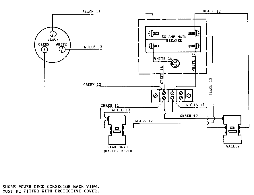
I checked the online manual, and wouldn't you know it, here is a picture of the wiring diagram.


Edited by - on
Go to Top of Page

skrenz
Captain

Members Avatar

USA
351 Posts

Response Posted - 03/28/2008 :  12:16:47  Show Profile
Here's a question. Should you bond your green grounding connector to the boats 12 v negative ground? I was reading an electrical check list created by Robb Zuk. He states that the green grounding connector should be connected to the "ships ground" or "common ground point". "grounds from batteries, engine, switch-panel negative bus bar, bonding system, auxiliary power generator, underwater ground plate, ship's 120 Volt safety-ground, and LORAN signal ground all meet at one point"

Ref: http://www.islandnet.com/robb/marine.html#CommonGroundPoint

Edited by - on
Go to Top of Page

Frank Hopper
Past Commodore

Members Avatar

Pitcairn Island
6776 Posts

Response Posted - 03/28/2008 :  13:47:28  Show Profile  Visit Frank Hopper's Homepage
I won't.

Edited by - on
Go to Top of Page

Dave5041
Former Mainsheet Editor

Members Avatar

USA
3758 Posts

Response Posted - 03/28/2008 :  15:32:49  Show Profile
I have read informed arguments for both approaches, so I don't think there is a wrong answer. I decided to go with separate grounds because I don't want to provide an easy path for stray current galvanic corrosion through my various submerged appendages to shore ground. That is opinion only - I am a reader, not not an engineer.

Edited by - on
Go to Top of Page

Dave Bristle
Master Marine Consultant

Members Avatar

Djibouti
10005 Posts

Response Posted - 03/28/2008 :  18:41:53  Show Profile
With DC, ground is one side of the circuit. With AC, ground is there for protection in case of an unplanned contact from the circuit. So, if an unplanned AC contact occurs and the ground is common between the two, do you end up with AC feeding into your instruments, battery, etc.?

Edited by - on
Go to Top of Page

Dave5041
Former Mainsheet Editor

Members Avatar

USA
3758 Posts

Response Posted - 03/28/2008 :  23:52:12  Show Profile
Since it is the ground side, current will follow the ground path away from your instruments if the ground is good. But then I shouldn't get 60 cycle interference in sensitive equipment when I plug it into a circuit that is also supplying an AC motor either, but but I sometimes do.

Edited by - on
Go to Top of Page

Dave Bristle
Master Marine Consultant

Members Avatar

Djibouti
10005 Posts

Response Posted - 03/29/2008 :  09:39:00  Show Profile
<blockquote id="quote"><font size="1" face="Verdana, Arial, Helvetica" id="quote">quote:<hr height="1" noshade id="quote"><i>Originally posted by Dave5041</i>
<br />...current will follow the ground path away from your instruments <i>if the ground is good</i>...<hr height="1" noshade id="quote"></font id="quote"></blockquote id="quote">...highly problematic. I've seen many cases where AC ground has enough resistance to be only partially effective. I don't know whether the little test plugs will detect that.

Edited by - Dave Bristle on 03/29/2008 09:40:00
Go to Top of Page

sweetcraft
Admiral

Members Avatar

USA
816 Posts

Response Posted - 03/30/2008 :  11:42:26  Show Profile
Dave's note caused me to go back and look at the diagram and the receptacles indicate they are GFI's which only one is possible in a circuit and the ground must be separate from the neutral. If the shore power is GFI protected the system shouldn't work because of the boat GFI and especially if the ground and neutral are connected. Your outside receptacles at home are suppose to be GFI protected and of course the dock receptacles. Then keep one hand in your pocket and test.(also called the smoke test)

Edited by - on
Go to Top of Page

Bruce Baker
Captain

Members Avatar

USA
402 Posts

Response Posted - 03/31/2008 :  14:53:37  Show Profile
This is possibly a stupid question: with AC, isn't polarity a moot point? That is, don't you have two leads that alternate between being hot? When I bought my house, my home inspector told me that some of my electical sockets had reversed polarity. How can that be?

On the other hand, I've heard of serious damage done to boat's elecrical systems because the polarity was wrong.

Edited by - on
Go to Top of Page

Dave Bristle
Master Marine Consultant

Members Avatar

Djibouti
10005 Posts

Response Posted - 03/31/2008 :  16:32:24  Show Profile
<blockquote id="quote"><font size="1" face="Verdana, Arial, Helvetica" id="quote">quote:<hr height="1" noshade id="quote"><i>Originally posted by Bruce Baker</i>
<br />This is possibly a stupid question: with AC, isn't polarity a moot point? That is, don't you have two leads that alternate between being hot? When I bought my house, my home inspector told me that some of my electrical sockets had reversed polarity. How can that be?<hr height="1" noshade id="quote"></font id="quote"></blockquote id="quote">Let's say you have a grounded light fixture. If the polarity is reversed, the switch is OFF, and you touch both the base of the light-bulb and the metal fixture (ground), you'll get a big surprise. If the polarity is right, the metal cup and therefore the bulb base are neutral, so the same scenario won't do a thing. (The contact at the bottom of the cup is hot.) Keeping AC polarity straight makes things safer. I got a lesson when cleaning a reversed chandelier with a damp paper towel.

Edited by - on
Go to Top of Page

Voyager
Master Marine Consultant

Members Avatar

USA
5377 Posts

Response Posted - 03/31/2008 :  20:32:37  Show Profile
Think of AC grounding this way. The hot swings plus 60V, then -60V - sixty times a second. The neutral also swings, but only relative to the hot, not to ground. There should be zero volts between neutral and ground in a properly grounded system.

As Dave points out, corrosion or a bad connection can interfere with proper grounding, so you often get a 'tickle' current. GFIs are intended to respond to this promptly, because if ALL the current coming out of the hot side does not return on the neutral, then the GFI will sense a fault and will POP the circuit.

Remember that 120VAC has, in reality, a peak voltage that is much greater than 120V. It's 169V. RMS or average voltage makes it read 120V on an AC volt meter. And that's why it is very 'surprising' when you get a dose from a miswired lamp.

All kidding aside, reversing 120 VAC polarity can kill.

Edited by - on
Go to Top of Page

skrenz
Captain

Members Avatar

USA
351 Posts

Response Posted - 04/01/2008 :  17:07:21  Show Profile
Especially if you're standing on a step ladder at the time...

Edited by - on
Go to Top of Page

Phredde
Navigator

Members Avatar

125 Posts

Response Posted - 09/07/2009 :  18:24:24  Show Profile
OK...well I procrastinated long enough and looked harder at my problem: sure enough the pigtail was wired backwards and a simple switch of black for white cleared things up ASAP. I was never able to find a polarity meter at any of my hardware stores, but what really helped was a simple description of AC wiring from Wiki:

http://wiki.answers.com/Q/How_do_you_test_ac_polarity_with_a_multimeter

How do you test ac polarity with a multimeter?

As applied to household AC conventions, there should be no voltage from N to Ground. Neutral is white, hot is black, ground is green. There should be voltage from black to N, Black to G, but not N to G.

Outlets are properly placed with the ground pin down, which puts N, to the left, and Hot to the right. Neutral is the wider one.

As applied to general electronics, the question needs a reference. There is AC, which takes two wires, and a Ground, which may be common to one lead of the AC, or separate, or exist at the center tap of a transformer, making each AC lead half the rms voltage of the lead to lead voltage.

Edited by - on
Go to Top of Page

Stu Jackson C34
Admiral

Members Avatar

844 Posts

Response Posted - 09/17/2009 :  10:03:00  Show Profile
<blockquote id="quote"><font size="1" face="Verdana, Arial, Helvetica" id="quote">quote:<hr height="1" noshade id="quote"><i>Originally posted by Phredde</i>
<br />I was never able to find a polarity meter at any of my hardware stores... <hr height="1" noshade id="quote"></font id="quote"></blockquote id="quote">

You need much better hardware stores!

Edited by - on
Go to Top of Page
  Previous Topic Topic Next Topic  
 New Topic  Topic Locked
 Printer Friendly
Jump To:
Association Forum © since 1999 Catalina Capri 25s International Association Go To Top Of Page
Powered By: Snitz Forums 2000 Version 3.4.06
Notice: The advice given on this site is based upon individual or quoted experience, yours may differ.
The Officers, Staff and members of this site only provide information based upon the concept that anyone utilizing this information does so at their own risk and holds harmless all contributors to this site.