Catalina - Capri - 25s International Assocaition Logo(2006)  
Assn Members Area · Join
Association Forum
Association Forum
Home | Profile | Register | Active Topics | Forum Users | Search | FAQ
Username:
Password:
Save Password
Forgot your Password?

 All Forums
 Catalina/Capri 25/250 Sailor's Forums
 Catalina 25 Specific Forum
 Mast Wiring - Grounding issue?
 New Topic  Topic Locked
 Printer Friendly
Author Previous Topic Topic Next Topic  

Ape-X
Admiral

Member Avatar

USA
662 Posts

Initially Posted - 06/17/2012 :  07:04:33  Show Profile
I replaced all wiring in the mast this spring, and finally getting to hooking up to power: I noticed some voltage problems: When switched on, everything appears ok, but off I am getting some transient voltage.

My setup: 2 NEW cables from the battery to battery switch 1 & 2. position 1 controls the original factory fuse panel position 2 runs to an aux fuse block for added equipment. Measuring voltage at the mast connector: 0.3v everything off, and small increments everytime a different circuit is turned on. for instance master on, 0.3V (0V to ground) then cabin lights on, mast voltage = 1.4V. Turn on the bow lt, 3V, then the appropriate ciruit, 12.8V. Battery position 2 and checking at the aux fuse block shows 0 and 12V with the battery switch.

1) hopefully I am looking at this correctly? I am wondering if it is fuse panel or wires to mast from the fuse panel.
2) looking at the wiring diagram for the mast lights, it would appear the green ground is solely for the mast (good news that I don't have to worry about the cabin lights being affected by the same mallody)
3) Has anyone replaced the wiring for the mast back to the fuse panel? It appears to be running within the fiberglass tab the builkhead mounts to. Is this glassed in as well with no hopes of pulling a new wire in the same conduit?
4) how far reaching does the problem appear to go??? ugh!

s/v No Worries, O'Day 28
PO Moe'Uhane - C25 SR/FK #1746

Edited by - on

redeye
Master Marine Consultant

Members Avatar

3476 Posts

Response Posted - 06/18/2012 :  05:03:22  Show Profile
<< it would appear the green ground is solely for the mast >>

Yep..

<< Has anyone replaced the wiring for the mast back to the fuse panel? >>

Yep...

<< Is this glassed in as well with no hopes of pulling a new wire in the same conduit? >>

Yep....

<< how far reaching does the problem appear to go??? ugh! >>

Just as far as each circuit.. OK well not really. but ya gotta look at it as replacing each circuit. One at a time and getting you head around it is not that hard. A relatively small DC circuit.... That being said it is some work. I will try to verbalize it in hopes it will be of assistance and forgive me If it sounds like I know the only way to go, as there are many ways to skin a cat.

Anyhoo.. the OEM wire is in the liner and pretty much inaccessible.

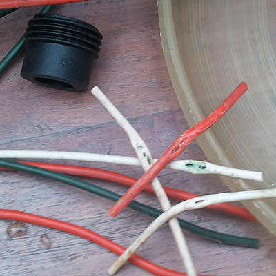
Wire that I could find and pulled out from that circuit was like this:


And other places OEM had a 3 way connector on the lighting circuit that was an uncovered metal connector that could cut insulation also.

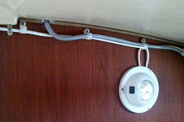
So ya got a mast circuit. 3 wire plus a ground going to the deck connector.. I ran it hanging from the wood strip behind the cabin lights and through the bulkheads with grommets. Screws in cable ties to hang the wire in the wood strip. 4-14 to the deck plug. I like the 4 prong black plastic deck plug from Catalina Direct.


Just wire your deck plug and change the connections at the panel till ya got it wired right. The green Ground is the only one ya gotta get right at the deck plug. Ground from mast wiring to ground in harness wiring. The other hot leads you can change out easy enough at the panel just by changing where they plug in ..

Might not be a grounding issue.. a power going to other circuits issue. I guess wires getting crushed in between the liner and deck.

Personally I don't like completely hidden wires on a boat. As soon as they disappear they develop a problem where you can't see it.

anyhoo.. I hope this helps.


Edited by - on
Go to Top of Page

Stu Jackson C34
Admiral

Members Avatar

844 Posts

Response Posted - 06/18/2012 :  14:00:40  Show Profile
<blockquote id="quote"><font size="1" face="Verdana, Arial, Helvetica" id="quote">quote:<hr height="1" noshade id="quote"><i>Originally posted by Ape-X</i>
<br />

My setup: 2 NEW cables from the battery to battery switch 1 & 2. position 1 controls the original factory fuse panel position 2 runs to an aux fuse block for added equipment.
<hr height="1" noshade id="quote"></font id="quote"></blockquote id="quote">

Something sounds weird here. A 1-2-B switch has two INPUTS, posts 1 & 2, and one OUTPUT, the C or common post. It sounds odd that it appears you have it wired so the battery output is the input to the C post and the 1&2 posts are being used to direct current to either of two panels.

How many batteries do you have and how is it wired?

Edited by - on
Go to Top of Page

Ape-X
Admiral

Members Avatar

USA
662 Posts

Response Posted - 06/18/2012 :  14:35:45  Show Profile
Stu, Great observation, something I don't remember all considerations given: I am flowing juice backward through the switch.....

I have one battery: and now need to verify how it is hooked up and can comment next weekend when there. With no voltage leak detedcted at the aux fuse panel, I was wondering about the entire stock panel, and started yanking fuses. Frustration won out, I went sailing and took a nap.

Edited by - on
Go to Top of Page

OLarryR
Master Marine Consultant

Members Avatar

USA
3467 Posts

Response Posted - 06/18/2012 :  14:50:54  Show Profile  Visit OLarryR's Homepage
I rewired the mast wiring to a new switch panel located below my sink near the companionway. Since I thought the wire from the cabin top was laid between the fiberglass liner and the cabin top, I drilled a hole at a sharp slope from within the deck connector hole so that the hole came out in front of the cabin bulkhead into the Head space up near the bulkhead rubber liner. I then wired it thru a hole in the little shelf behind the head and then behind and under the seats in the main cabin to the new switch panel.

Now this may be different than your boat since I have an '89 but contrary to what I thought that the old wiring ran between the cabin top and fiberglass liner, I was removing old wiring no longer attached to my switch panel and ran forward under the port side of the bilge cover area. After giving it a strong tug, it came out....down the mast column ! That was the pre-existing mast wire. It was not laid between the cabin top and liner as I previously thought but actually went straight down the mast column inside the cabin and then under the port side of the bilge cover opening and back to the switch panel. It was a very snug fit inside the deck connector hole and so I worngly assumed that it was permanently between the cabin top and liner but it turned out not to be the case. Not sure if all have mast wiring run thru the deck connector hole and down the mast column in the cabin or just the later models.

Edited by - on
Go to Top of Page

Ape-X
Admiral

Members Avatar

USA
662 Posts

Response Posted - 06/29/2012 :  06:12:49  Show Profile
Last weekend I got a look at the wiring and checked against some basic DC circuits.

The battery switch is a switch: so what direction the current is flowing through said switch is inconsequential. I have found some redundency in my current wiring, but nothing that should account for the current leak. So the prognosis is the wiring to the mast is corrupt.

My wiring: pos lead to common battery switch, which then branches out to two circuits via bat1 and bat2. Bat1 leads to the factory fuse panel, bat2 to an aux fuse block. That then branches out to the individual curcuits, returns to the panel and finally to the neg terminal. Now current flow is actually from the neg terminal to the positive. With the switches originally setup on the pos leg though, it is easier for me to visualize opposite the actual current flow.

Stay tuned for final wiring for the mast, as I wont be at the boat until after the 4th. :O( At least I had the wiring up to that point in correctly.

Edited by - on
Go to Top of Page

tweeet65
1st Mate

Members Avatar

USA
55 Posts

Response Posted - 07/03/2012 :  14:29:47  Show Profile
Mates,

I have 2 batts but only number 2 is connected to the 1 - 2 switch, the common goes to the panel (bat 1 is just to my yamaha). When I tested the panel(after I rewired all and added an anchor lite at mast top)my cabin lights lit and my spreader (the one aiming up) was on though very dim. It feels like I may have a ground issue. My original question was does the green mast gnd wire need to go somewhere other than the ground side of the distribution panel? To the keel or some such other ground? the manual says it is grounded "seperately" but does'nt say where or to what.

dave

Edited by - on
Go to Top of Page

Ape-X
Admiral

Members Avatar

USA
662 Posts

Response Posted - 07/04/2012 :  07:12:14  Show Profile
on my panel, the black and green gnd (-) are connected via a y-connector, both leading to a bus bar on the backside of the panel behind the sink and cooler. It appears to be factory.

I have yet to re-wire maast to the panel: it is hard to get enthusiastic about drilling and re-routing the wires between the liner and hull

PS: THANKS RedEye for the likely root cause.

Edited by - Ape-X on 07/04/2012 07:14:22
Go to Top of Page

Stu Jackson C34
Admiral

Members Avatar

844 Posts

Response Posted - 07/04/2012 :  09:38:28  Show Profile
Green should NOT be in a DC circuit. See the other "ground" topic for a link to a grounding vs. bonding link.

I still think you need to get your head(s) around how a 1-2-B switch works. It should be a "use" switch, the batteries FEED into the switch to the 1 and 2 posts. The C post is the "output" of the switch to the loads, i.e., the distribution panel. The batteries should NOT be connected to the C post.

Edited by - on
Go to Top of Page

Voyager
Master Marine Consultant

Members Avatar

USA
5383 Posts

Response Posted - 07/04/2012 :  11:15:21  Show Profile
I agree - unless you have 2 batteries, you don't need a 1-2-B switch at all.

I would suggest that you connect all the (-) negative wires from ALL your devices (lights, gauges, radios, cigarette lighter outlets, common wire in the mast and the (-) negative cable from the engine alternator) to a heavy buss bar, and connect the buss bar to the (-) terminal of the single battery. There should never be a fuse or switch on the negative side of the house or alternator circuit.

I'd connect the (+) cable from the engine alternator through a 60 Amp fuse to the (+) terminal of the battery. This should be a home run of 10 gauge or 8 gauge cable.

Then I'd connect an 8- or 10-gauge cable from the (+) terminal of the battery through a 30 Amp fuse to the power panel(s) (it seems you have two panels???) If you do have two, you can either power them separately or in parallel (daisy chain). There should be NO (-) negative connection going to the power panels at all - it should only switch (+) power to each of the devices. If you like, you can have a master shut-off for the panel - an additional switch that kills all the circuits in the panel, irrespective of the position of any on/off switch. Most panels have a master switch for this purpose.

From the power panels, I'd check that battery voltage (+12.6V +/- 0.4V) reaches each device. With a voltmeter and a helper, with the main power on, switch the power on and off from each switch and measure voltage from the (+) lead to the buss bar. You may need to extend the wire so your voltmeter will reach.

If you get any less than 12.6 +/- 0.4 volts, (like 9V or 3V) you may have two devices in line (in series where the (+) cable from one leads to the (-) cable of the other), or your wire gauge may be too small (i.e.: an electric winch fed by #16 gauge wire). Physically trace the wires in either case.

Even if the cable jacket is not marked with a gauge # (e.g.: AWG-16, 12, 10, 8, etc), if you have a wire stripper tool with multiple stripper holes, you can size up the conductor wire in question (not the jacket) with the hole in the stripper jaws, and there will be a wire gauge marked next to each hole.

If you don't have a master turn off switch for everything, you could use your 1-2-B switch as that. Connect the battery (+) cable to connection post 1, and connect the panel (+) feed to Common connection post. To turn on the boat power, turn the switch to 1. To turn it off, turn the switch to OFF.

If you ever get a second battery, you can connect the 2nd battery (+) through a 30 Amp fuse to connection post 2. Always keep your main battery directly connected to the alternator. If you want to charge battery 2, while running your engine, switch the 1-2-B switch to both.

Unfortunately, there's no substitution to tracing out all your wires and writing down the color codes, and creating a wiring diagram as you go. When I rewired <i>Passage</i> I did just that.

The only problems I found were the alternator (+) feed ran through the master shutoff - I corrected that. Also the bow running light wire had been chafed in the anchor locker, the deck connector to the mast was "touchy" although the mast wiring was fine, the voltage was reversed on the cabin interior lights (but it was that way from the factory), and the small copper buss bar behind the panel had developed corrosion. Also the mast-top VHF antenna was no longer connected or working, but the aft rail one works fine. Otherwise, no serious issues.

Common sense, careful documentation, patience and time are key ingredients. Don Casey's sailboat electrics is a great reference book. By the way, these comments all refer to 12V wiring in the boat. Do not mess with shore power, 110VAC outlets, appliances, lighting or fixtures. Leave that to a licensed electrician.

Edited by - Voyager on 07/04/2012 11:16:17
Go to Top of Page

Stu Jackson C34
Admiral

Members Avatar

844 Posts

Response Posted - 07/04/2012 :  11:33:42  Show Profile
I agree wholeheartedly with Bruce except for the last part about 110V wiring. There's no reason you can't learn how it works, too. Actually, you'd be safer learning it, 'cuz if an "electrician" does it, there's no guarantee HE knows what he's doing! Really, been there, done that. It's not that hard, three wires instead of two. :)

Edited by - on
Go to Top of Page

Voyager
Master Marine Consultant

Members Avatar

USA
5383 Posts

Response Posted - 07/04/2012 :  21:37:54  Show Profile
Stu
My rule is crawl, walk, run. 12 volts will burn your boat down to waterline as surely as shore power will.
But 120VAC is lethal - I've seen too many times when appliance power leads are reversed, so if you touch the fridge and the lamp's pull chain - you're done. No coming back.

Edited by - on
Go to Top of Page

Stu Jackson C34
Admiral

Members Avatar

844 Posts

Response Posted - 07/04/2012 :  22:29:05  Show Profile
Bruce, that's exactly my point. What you DON'T know about is what can getcha. Learn, learn and learn, then you can fix it. There ain't no boat mechanics out on the water, or, for that matter on the docks.

If you can learn two wires, you can learn three.

Edited by - on
Go to Top of Page

redeye
Master Marine Consultant

Members Avatar

3476 Posts

Response Posted - 07/05/2012 :  19:34:31  Show Profile
Dear lord.... I hope the boat next to me was not wired by somebody just learning 120vac.

Edited by - redeye on 07/05/2012 19:42:12
Go to Top of Page
  Previous Topic Topic Next Topic  
 New Topic  Topic Locked
 Printer Friendly
Jump To:
Association Forum © since 1999 Catalina Capri 25s International Association Go To Top Of Page
Powered By: Snitz Forums 2000 Version 3.4.06
Notice: The advice given on this site is based upon individual or quoted experience, yours may differ.
The Officers, Staff and members of this site only provide information based upon the concept that anyone utilizing this information does so at their own risk and holds harmless all contributors to this site.