Notice:
The advice given on this site is based upon individual or quoted experience, yours may differ.
The Officers, Staff and members of this site only provide information based upon the concept that anyone utilizing this information does so at their own risk and holds harmless all contributors to this site.
Went sailing on the SF Bay last weekend (see the post on furling jib lessons). Anyway, the wind was blowing a bit through Racoon Straight (25+ best estimate), and, as you'd suspect, there was some weather helm. A bit. More during gusts, which were frequent.
During one such gust, I found myself leaning on the wheel to keep heading in the direction wanted, and suddenly felt a bit of a lurch in the steering. It *felt* like a chain jumping a sprocket...
I was more careful with the helm thereafter, and felt/saw no more problems, but I still want to check out the steering. I welcome any and all suggestions about where to look - and what to look for - to be sure I don't loose my steering next trip out to the Bay!
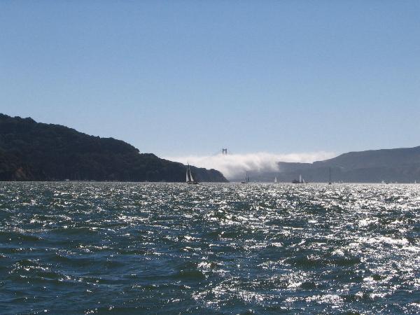
By the way - below is a pix of the straights from the "side" (less wind) later in the day - Angel Island on the left, Marin on the right, and the Golden Gate (with fog) behind.
You might want to try a search of posts from the past couple of years. A C250 owner at my marina had to do a fairly extensive "redo" of his wheel steering. And, posted the information for other C250 owners on this message board. I don't remember the details - but there was a considerable discussion.
I've seen a lot of discussion about upgrades and modifications, and have read many of those. (there's a *lot*!)
I took the pedestal apart: no apparent damage to the sprocket or chain. Looked at the cables below; again, no apparent damage. Guess I just need to take my chances and assume no harm's been done.
You narrate a problem of the Edson wheel steering system on the 250 that I have commented on during my quest to tame the beast. The basic problem is an inadequate steering ratio (poor wheel to rudder leverage).
Catalina uses and Edson small boat steering system on the 250 that uses flexible cables. The original push/pull (single cable) should be upgraded but you seem to describe a slipping chain which may mean you have the upgraded two cable system. Both systems suffer the steering ratio problem but it is less manifest with a 3rd generation balanced rudder.
With the 2nd generation unbalanced rudder, the steering ratio does not provide the neccessary leverage to deal with rudder torque and because of necessary play might slip over the chains teeth.
Verify what you have, if the system has two cables and if play exist, inspect the mounting bracket for the cables on the inside of the transom to ensure that the two sides hare not bent inward. If so, it has been reported that a fix can be effected by fitting a wooden spreader between the two sides to hold them from bending inward. After a spreader is affixed with the two sides repositioned, place the rudder hard over and adjust the cables for no play. Note: There will be some play at center position, hopefully not enough to allow the chain to jump. Do not ajust for no play in the center position as when the rudder is swung, the cables will taughten and may place increased loads on the cables and increase drag and prematurely wear them.
If the system is single cable, I'd suggest upgrading because the design has numerous problems and failure potentials. There are two options, an Edson upgrade or an open wire conversion design. The Edson upgrade is not very suitable to the 2nd generation rudder because it doesn't solve the leverage requirements needed with that rudder.
The open wire design can be self built or bought as a kit. It provides a more than doubled ratio over the Edson design and has no play and minimum drag compared to the fairly high levels of drag of the Edson cables. It is less expensive (half the price), simple to install and easily repaired from local parts. The open wire system is in my opinion a superior design compared to using flex cables.
C250 loads during heeling are in the realm of those on larger boats which all use open cable designs. The reason is simple, open cables can be designed to fit the steering ratio needed to deal with various loads. The Edson steering system using the flex cables is limited by design to a poor steering ratio. Here is more than asked for but might be found interesting.
In the first design, a longer steering arm to gain leverage could have been used but for the travel limitations of the idler chain within the pedestal. In the newer pull/pull system, the arc of the rudder arm limits the travel because cables are hooked to both sides of the steering arm. The upgraded system suffers the need to have play or deadband near the wheels centered position. This play allows for the taugtening of the cables as the rudder is swung hard over. A normal rudder connection uses a quadrant to avoid this problem and provide the desired steering ratio. The Edson small boat steering system upgrade which does not employ a compensating design to deal with the arc of the rudder arm, will then either suffer too much deadband or play with the rudder centered or friction from tightening cables in the rudder over positions. A longer steering arm won't work because the center deadband (play) would be far too great.
The open wire design uses a rudder arm extension which more than doubles the leverage and compensates for the arc which means that the system has no play at any point of travel because the cable tension remains the same, rudder lock to lock.
In my opinion the Edson small boat steering system using flex cables is not adequate. For example, the heavy effort currently needed as described above in your post where one has to lean all ones strength and energy to hold the wheel will be transformed by the open wire design to one in which a child can easily manage. What this means is that the system will now work with a wheelpilot where before it would not.
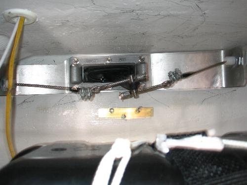
I've looked at your conversion before: now, it looks even better as a fall/winter project. I've attached a pix of the dual cable installation - it looks like I could reuse the existing cable.
I have access to a machine shop (good thing my brother-in-law likes me!). Would you be willing to sell detailed drawings of your kit? I also need to check if the conversion would fit with the bracket in place, or if it would have to be pulled.
Kevin, it looks like you have an awful lot of play in your system. Your steering arm should not be twisted and hanging down like the photo shows. Actually, it looks more like the way mine hangs when the rudder is off the boat. The manual I received from Edson says there should be no more than one inch of play in the cables at the center helm position when adjusted properly. Aryln gave you one of the adjustment methods, but make sure you make the same amount of turns on each adjusting screw or you could just make the measurements the same on both sides of the adjusting nut.
Frogger, I hesitated to make any judgements about the play because it does appear that the rudder arm is disconnected, but it does apear that the attachment points on the axle shaft are inverted.
I thought that also, but difficult to tell from the picture. Kevin, make sure the pointed end of the adjustment barrel nut is aimed at the rudder control arm and the standard nut is on the end of the screw it locks the adjustment barrel nut in place.
Yes, the conversion would make a good winter project and it sounds like you have the inside track to the required machining equipment.
A freely offered rough set of plans exist on my web site but needed is some dimensioning, will try to do that soon.
Yes, its possible that the cables might be long enough. I've been supplying two - nine foot lengths, but don't know how much extra is being cut off. Maybe someone who has converted will remember?
At question would be the chain length. My design uses about 2.25 total turns of the wheel compared to one turn of the Edson design. Those of us making the conversion have been using the existing chain, but I think the chain is a common size and easily available. It is very easy to attach the wire rope to the chain.
I don't think the transom bracket would present any problems to the open wire conversion.
Arlyn - I've a printout of your rough drawing in front of me as I type this. However, while mechanically inclined, I'm *terrible* at drawings, so if you *are* able to get some dimensions, that would be great!
Frogger - as Arlyn thought, the pix was taken without the rudder attached. When on, free play is minimal. I *will* take a look at the connections, though, with your advice in mind. Thanks!
Arlyn, I've got the plans for my non-C250 conversion in Autocad still. I can modify that plan and give it back to you to post if you get me the dimensions for a C250 version.
By the way I can now report that the system works great. I have had the boat out now in some pretty windy stuff and it works fine. Last time we went out at Santa Barbara I asked my 8 year old son to take the wheel while I raised the main. I never got it back. He drove for over 3 hours as the winds built, then his mom took over. All I could do was trim sails. (at least until we re-entered the busy little harbor, then nobody wanted to touch it)
Thanks Todd, I didn't see your message until after I made a drawing using Mircrosoft Paint... a bit crude but readable.
You offered a great sailing report which agrees with others especially considering your rudder arm had less length than what is being used on the 250. Note: Todd's boat has a cockpit scupper drain that limited the rudder arm extension.
This discussion brings up again the issue of choice between wheel steering and tiller. The same arguements remain for both with the exception that previously on the 250, the arguement couldn't be made that a wheel was easier to helm, in fact, it requred greater effort. The open wire conversion changes that and provides that even a child can handle the wheel in windy conditions without strength concerns.
I'm crossing my fingers that you've got a C-25. I need to convert to Arlyn's open-wire system on my boat ... I've already crawled around back there and taken some preliminary measurements ... it looks to me like the installation will be considerably more difficult on a C-25.
Also, I couldn't get the link to work in Arlyn's post ... so, would you mind sending me the drawing you did? My regular email address is buzzmaring at AOL dot com ... thanks!
Sorry Buzz, I can't offer you dimensioned plans for a C25. I have a Laguna 26. Very similar to C25 with a little more volume. The aft end is more like the C250 though with a large berth under the cockpit sole. I'd be happy to share my drawings with you. If you can manipulate Autocad you can modify them to suit your boat. I found the acurate cad drawings invaluable to aid me in the planning. Especially the placement of the hole in the transom for the rudder arm. Just got a new computer so I will have to fire up the old one, now in the kids room to resurect the file.
<blockquote id="quote"><font size="1" face="Verdana, Arial, Helvetica" id="quote">quote:<hr height="1" noshade id="quote"><i>Originally posted by tmhansen</i> <br />Sorry Buzz, I can't offer you dimensioned plans for a C25. I have a Laguna 26. Very similar to C25 with a little more volume. The aft end is more like the C250 though with a large berth under the cockpit sole. I'd be happy to share my drawings with you. If you can manipulate Autocad you can modify them to suit your boat. I found the acurate cad drawings invaluable to aid me in the planning. Especially the placement of the hole in the transom for the rudder arm. Just got a new computer so I will have to fire up the old one, now in the kids room to resurect the file. <hr height="1" noshade id="quote"></blockquote id="quote"></font id="quote">
Hi Todd,
Arlyn was kind enough to email the drawing to me ... I assume it is the one he made using Microsoft Paint ... Arlyn mentioned that it is a bit "crude," but it looks really good to me.
I'd like to see the cad drawings you made, but I don't want to put you through a lot of trouble ... so, if it's going to be a big hassle to find the file, I can make do with Arlyn's drawing. Otherwise, you can send it to buzzmaring at AOL dot com.
Buzz, my current drawing is of the components. You would benefit from Todds drawing because it is a scale drawing of the placement of the system and details the swing of the rudder arm.
You will note that my system uses a frame which requires 17" each side of center line. That could be reduced by about 3" which would then require 14" each side of center for the mounting frame. That may be a problem considering the quarter berth.
However, there are other methods to accomplish the task that would avoid the wide frame and still produce a better lever arm.
Notice: The advice given on this site is based upon individual or quoted experience, yours may differ. The Officers, Staff and members of this site only provide information based upon the concept that anyone utilizing this information does so at their own risk and holds harmless all contributors to this site.